Front panel controls and operating modes, F ront panel controls and operating modes – Time Electronics 1048 Voltage-Current-Loop Calibrator User Manual
Page 4
4
V1.2 30/12/10
P a g e
| 4
1048 Technical Manual
2.
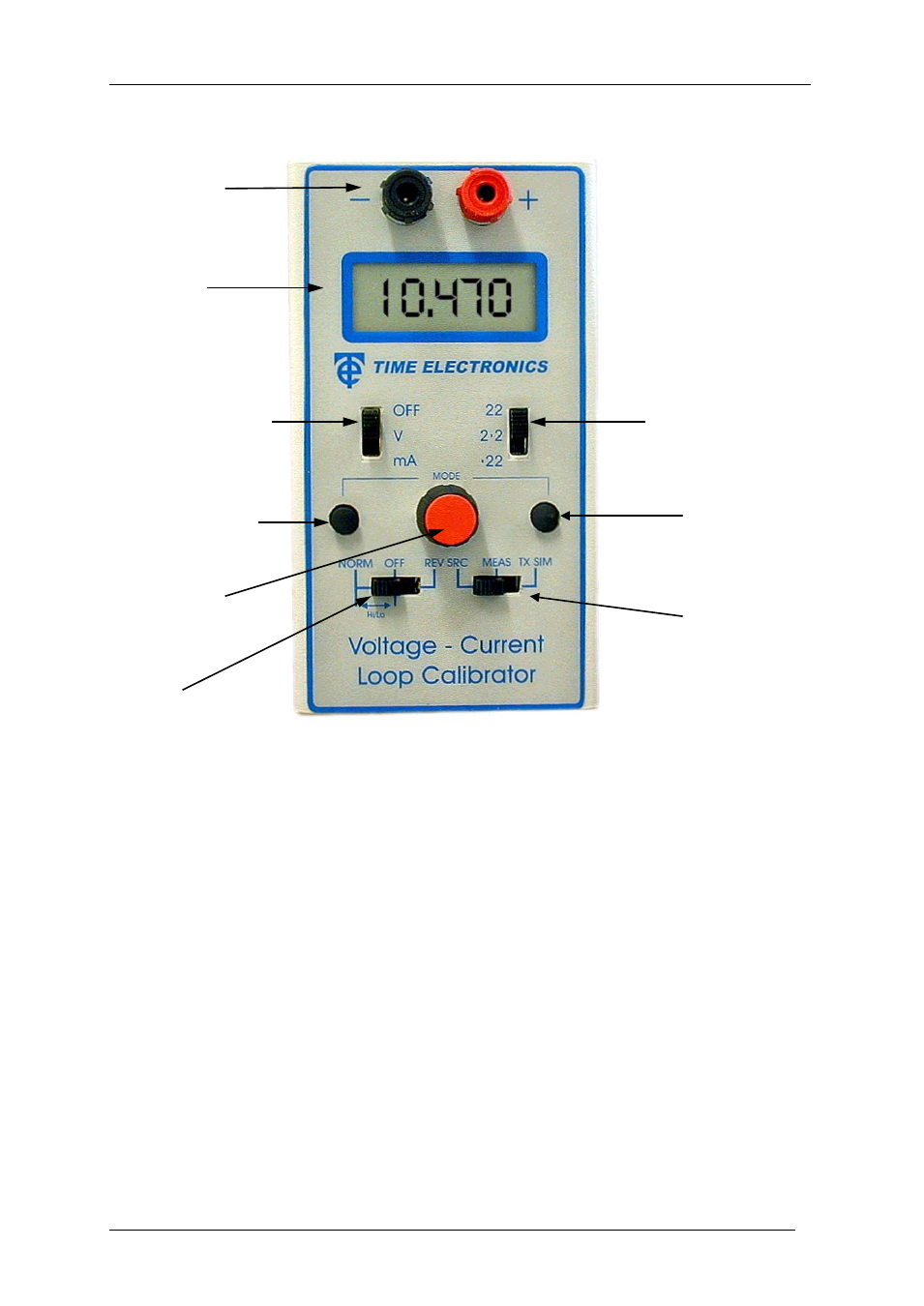
F ront panel controls and operating modes
A. Input/Output terminals
B. 4.5 Digit LCD Display.
C. 3 position switch for ON/OFF( OFF), Volts (V), Current (mA).
D. Push button for fine decreasing (DEC) of the output.
E. 10 turn control for coarse output adjustment
F. 3 position switch, normal (NORM), zero (OFF), reverse (REV) output. Also used to
restore high resolution display.
G. 3 position range switch (22, 2.2, 0.22).
H. Push button for fine increasing (INC) of the output. Also used in conjunction with the
DEC button to select the modes of operation i.e. Normal, Step, and Ramp. When in
Step mode, it initiates automatic stepping. When in Ramp mode, it re-starts the ramp.
I.
3 position function switch for source (SRC), measure (MEAS), and transmitter
simulation (TX SIM).
B. Display
C. OFF/V/mA switch
D. Decrement (DEC)
A. Terminals
E. Multi-Turn
Output Control
F. Output switch
G. Range switch
H. Increment (INC)
I. Function switch