Controls, Controls diagram and key, C ontrols – Time Electronics 1030 Voltage & Current Source User Manual
Page 6
6
1030 Technical Manual
P a g e
| 6
3.
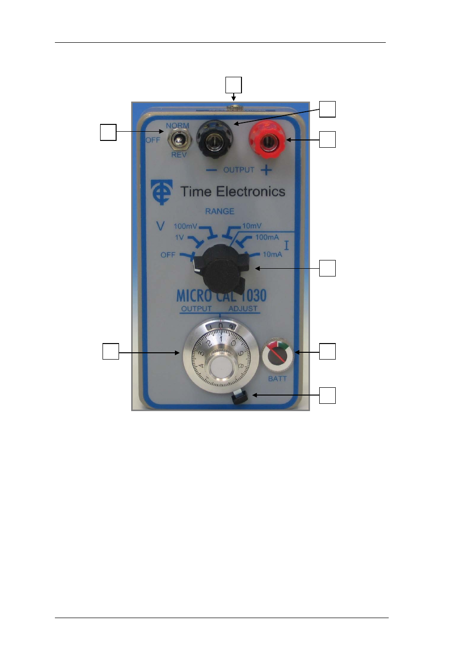
C ontrols
3.1. Controls Diagram and Key
1) Black 4mm terminal Negative output terminal.
2) Red 4mm terminal Positive output terminal.
3) 3 Position switch Selects Normal/Off/Reverse output
4) 6 Position rotary switch Selects range and turns instrument on
5) 10 turn potentiometer Selects required output
6) Potentiometer lock Right position is free, left is locked.
7) Battery level indicator Warns of battery failure
8) Recharge socket For recharging Ni-Cad cell (if fitted)
8
1
2
4
7
6
5
3