Module and trimmer location, Fig. 2 – Time Electronics 1030 Voltage & Current Source User Manual
Page 14
14
1030 Technical Manual
P a g e
| 14
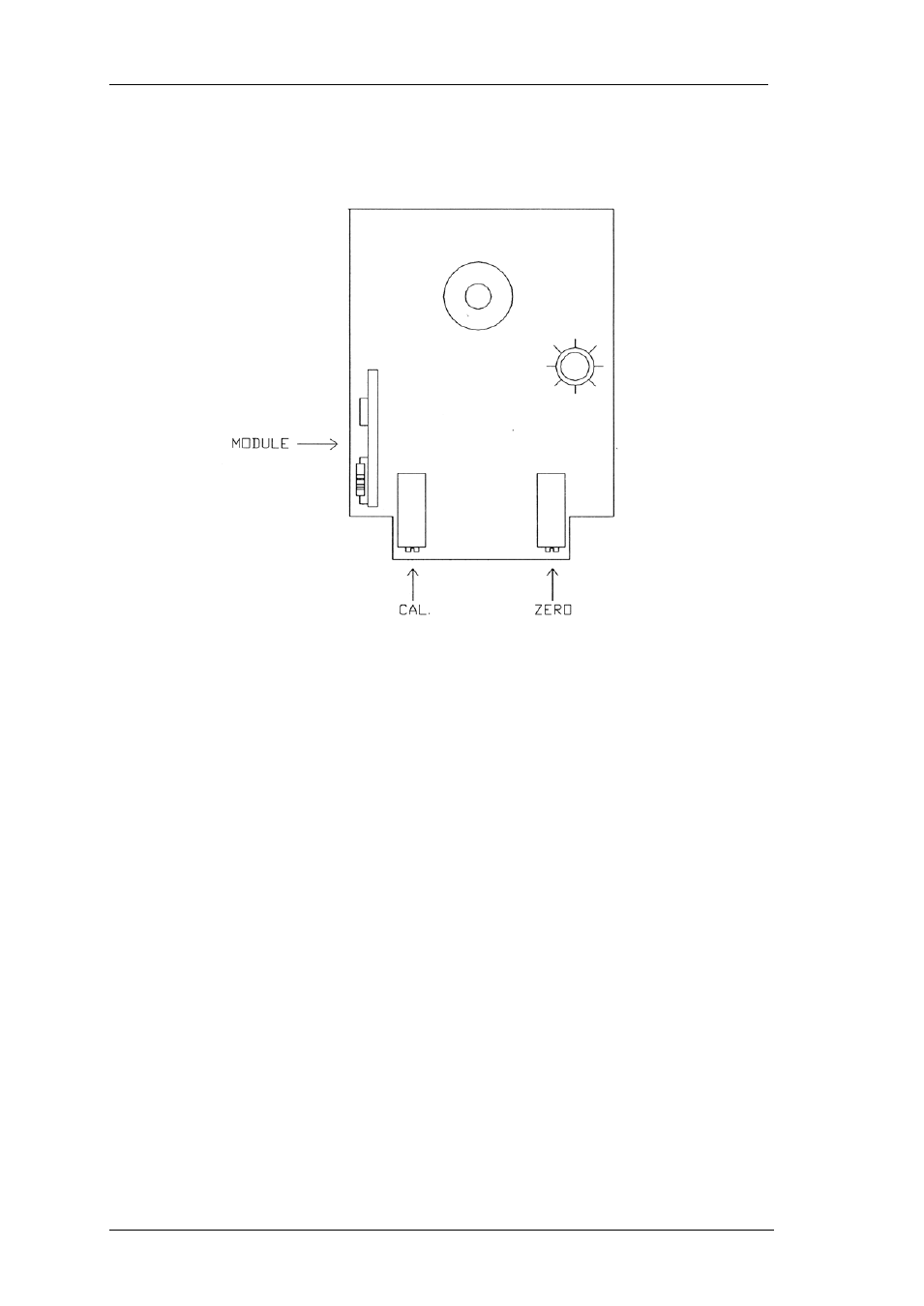
7.2. Module and Trimmer Location
11 Turn the output adjustment pot. to full scale, and adjust the full scale calibration
trimmer until the DVM reads 100mV.
The full scale for the instrument is then set up correctly.
The other ranges do not normally require calibration, and therefore are not fitted
with trimmers.
Should calibration become necessary, adjust or replace the resistors listed
below.
10mV F.S.
R6
10mA F.S.
R9
100mA F.S.
R5
12 The instrument can now be reassembled.
Fig. 2