Precision Control Systems ChamberIR 4069 User Manual
Page 16
5-3
5.5 ELECTRICAL
CONNECTIONS:
The Model 4069 is supplied with two 12-
foot (254 mm) power cable bundles. The cable bundles consist of the power wires for the
lamps and fan, as well as control wires for the thermostat (TSTAT), water flow interlock
switch (WFIS), and heater open interlock switch (HILS). If the Model 4069 was ordered
without the "PC" option, the wires are not terminated into a connector. It is the
customer's responsibility to hard wire the heater into the power control system. Wiring
diagrams can be found in the Appendix.
Note: The heater should never be directly wired into a voltage source. The heater should
always be wired into a power controlling system.
THERMOSTAT (TSTAT): The Model 4069 is supplied with a thermostat (TSTAT) to
protect from overheating. The TSTAT protects the heater from overheating only if the
TSTAT is properly wired into the control interlock of the power control system. The
TSTAT should be wired into a disconnect relay of the power controller/system. If the
TSTAT "open" (trips), the disconnect relay of the power control system should remove
power to the Model 4609 Heater. The TSTAT is mounted to the backside of the last
reflector before the cooling fluid exits the heater. The TSTAT has a fixed trip
temperature of 160ºF. If the reflector reaches 160ºF, the TSTAT will "open" and will not
"close" (reset) until it cools down to 130ºF.
WATER FLOW SWITCH (WFIS): Water-cooling is required for proper and safe
operation of the Model 4069. The heater is supplied with a Water Flow Interlock Switch
(WFIS) to ensure that it has water-cooling going through the reflectors, to protect from
overheating. The WFIS protects the heater from overheating only if the WFIS is properly
wired into the control interlock of the power control system. The WFIS should be wired
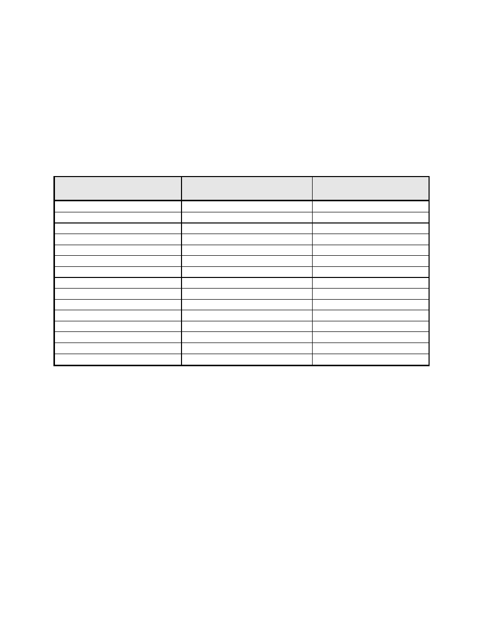
Model Number
System Voltage
(3 phase)
System
Amperage
4069-12R-10L-12kW-240V-PC-XX
240
29
4069-12R-10L-12kW-480V-PC-XX
480
15
4069-12R-10L-24kW-240V-PC-XX
240
58
4069-12R-10L-24kW-480V-PC-XX
480
29
4069-12R-16L-19kW-240V-PC-XX
240
47
4069-12R-16L-19kW-480V-PC-XX
480
24
4069-12R-25L-30kW-480V-PC-XX
480
37
4069-12R-38L-46kW-480V-PC-XX
480
55
4069-18R-10L-18kW-240V-PC-XX
240
44
4069-18R-10L-18kW-480V-PC-XX
480
22
4069-18R-10L-36kW-480V-PC-XX
480
43
4069-18R-16L-29kW-240V-PC-XX
240
70
4069-18R-16L-29kW-480V-PC-XX
480
35
4069-18R-25L-45kW-480V-PC-XX
480
55
4069-18R-38L-68kW-480V-PC-XX
480
83
Table 5-1. Electrical System Requirements