KYORITSU 6315 Quick Manual User Manual
Page 11
Wiring check
- 9
NG judgment
Wiring check
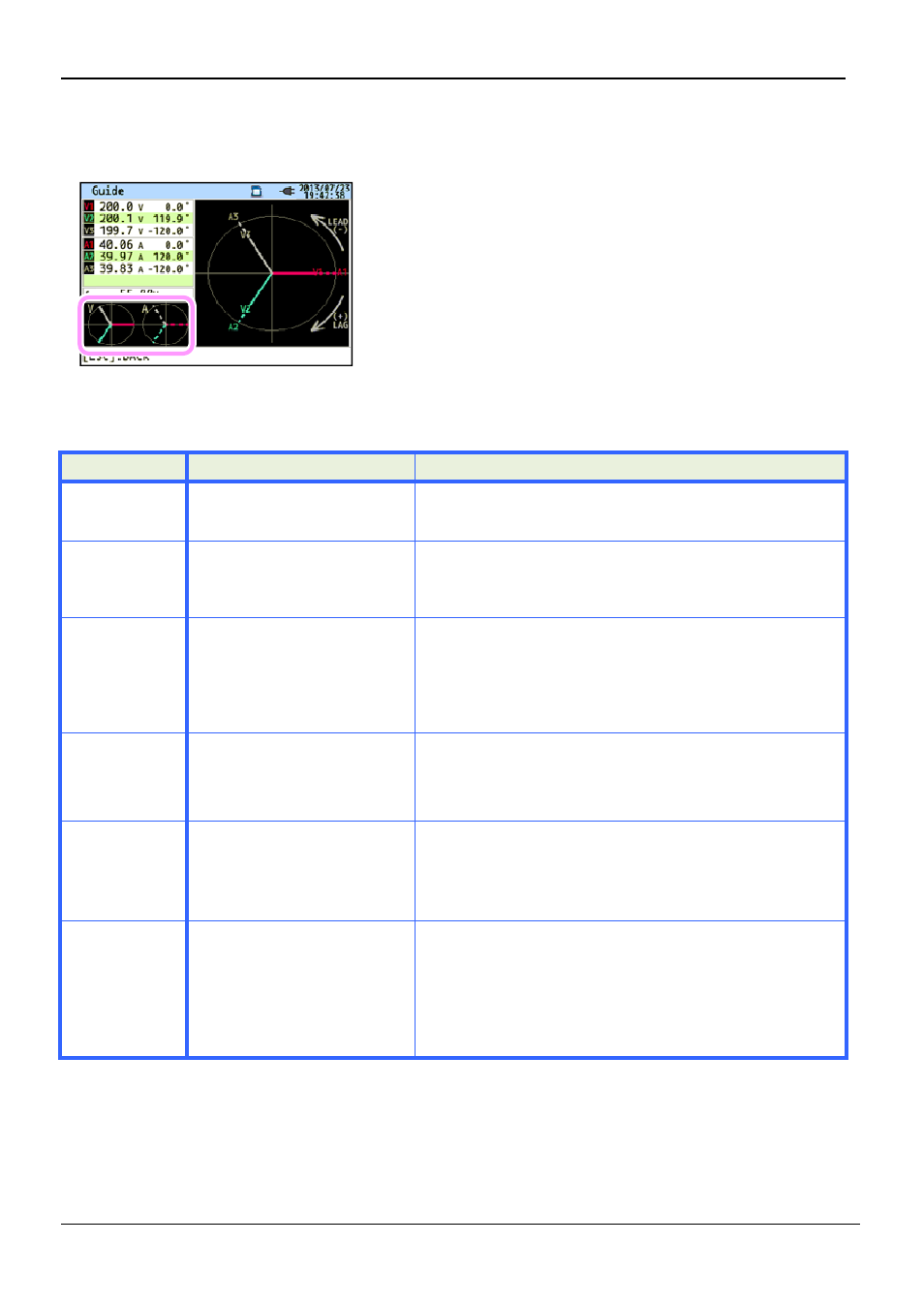
Close the result display. Then, the blinking vectors and the
values of NG items will be displayed. If all the results are
OK, the ideal vector diagram will be displayed at the lower
left corner.
Criteria of judgment and cause
Check
Criteria of Judgment
Frequency
Frequency of V1 is within 40
- 70Hz.
- Voltage clip is firmly connected to the DUT?
- Measuring too high harmonic components?
AC voltage
input
AC voltage input is 10% or
more of (Nominal voltage x
VT).
- Voltage clip is firmly
- Voltage test lead
AC v
Voltage
balance
AC voltage input is within
±20% of reference voltage
(V1).
* (not checked in
single-phase wiring)
- Settings are matched with the wiring system under
test?
- Voltage clip is firmly connected to the DUT?
- Voltage test lead
AC v
Voltage
phase
Phase of AC voltage input is
within ±10º of reference value
(proper vector).
- Voltage test leads are properly connected?
(Connected to proper channels?)
Current
input
Current input is 5% or more
and 110% or less of (Current
Range x CT).
- Clamp sensors are firmly connected to the Power
input terminals on the instrument?
- Setting for Current Range is appropriate for input levels?
Current
phase
- Power factor (PF, absolute
value) at each CH is 0.5 or
more.
- Active power (P) at each
CH is positive value.
- Arrow mark on the Clamp sensor and the orientation
of flowing current coincide with each other?
(Power supply to Load)
- Clamp sensors are connected properly?
KEW6315
9 -
KEW6315
Close the result display. Then, the blinking vectors and the
values of NG items will be displayed. If all the results are
OK, the ideal vector diagram will be displayed at the lower
Causes
Voltage clip is firmly connected to the DUT?
Measuring too high harmonic components?
Voltage clip is firmly connected to the DUT?
Voltage test lead is firmly connected to the
AC voltage input terminal on the instrument?
Settings are matched with the wiring system under
test?
Voltage clip is firmly connected to the DUT?
Voltage test lead is firmly connected to the
AC voltage input terminal on the instrument?
Voltage test leads are properly connected?
(Connected to proper channels?)
Clamp sensors are firmly connected to the Power
input terminals on the instrument?
Setting for Current Range is appropriate for input levels?
Arrow mark on the Clamp sensor and the orientation
of flowing current coincide with each other?
(Power supply to Load)
Clamp sensors are connected properly?