Instrument layout – KYORITSU 4300 User Manual
Page 10
̶ 8 ̶
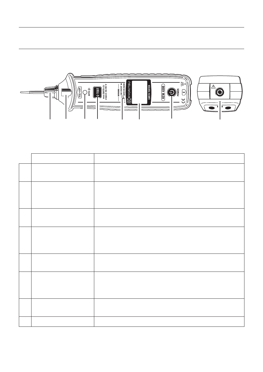
4. Instrument layout
(1) Instrument Body
Name
Details
1 H+S(C+P) terminal
To connect the replaceable metal tip MODEL8072
has been installed and delivered.
2 LED light
To illuminate the measurement spots
The light turns on/off automatically in relation to
ambient brightness.
3 Ambient light sensor
To sense ambient brightness for turning on/ off
the light
4 Test button
To conduct resistance measurement
Measurement is conducted when the button is held
down.
5 Warning LED
To give warnings for live circuit (blinking red)
and for large earth voltage (blinking yellow)
6 LCD
LCD with backlight
The backlight turns on/off automatically in relation
to ambient brightness.
7 Power button
To power on/ off the instrument.
The button should be held down for 1 sec or longer.
8 E terminal
To connect the test lead MODEL7248
5
6
3 4
7
2
1
8
Fig. 4-1
- 1009 (13 pages)
- 1011 (12 pages)
- 1012 (12 pages)
- 1018 (1 page)
- 1030 (1 page)
- 1061 (58 pages)
- 1051 (40 pages)
- 1109S (36 pages)
- 1110 (1 page)
- 2000 (1 page)
- 2002PA (27 pages)
- 2007A (1 page)
- 2009R (33 pages)
- 2012R (2 pages)
- 2017 (1 page)
- 2031 (1 page)
- 2033 (9 pages)
- 2040 (2 pages)
- 2046R (2 pages)
- 2200 (3 pages)
- 2210R (1 page)
- 2300R (1 page)
- 2413F (24 pages)
- 2413R (24 pages)
- 2431 (2 pages)
- 2432 (1 page)
- 2433R (1 page)
- 2434 (10 pages)
- 2500 (1 page)
- 2608A (2 pages)
- 3005A (24 pages)
- 3021 (24 pages)
- 3121A (12 pages)
- 3126 (28 pages)
- 3127 (60 pages)
- 3128 (88 pages)
- 3131A (20 pages)
- 3132A (20 pages)
- 3161A (24 pages)
- 3321A (24 pages)
- 4105A (10 pages)
- 4106 (48 pages)
- 4116A (20 pages)
- 4140 (32 pages)
- 4200 (24 pages)