Instrument layout – KYORITSU 4202 User Manual
Page 8
̶ 6 ̶
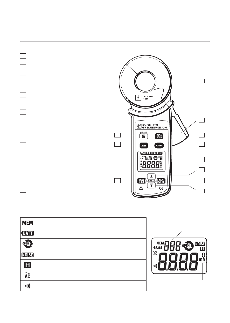
4. Instrument layout
Symbols to be displayed on the LCD
1
2
6
3
4
5
7
8
9
11
10
Name of each parts and buttons (for MODEL4200 and KEW4202)
1 Transformer jaw
2 Trigger
3 Backlight button
Switches on/off the backlight.
4 Function button
Switches ACA/ Earth resistance
functions.
5 Memory mode button
Check the measured value by
Data number.
6 Data hold button
Freezes/ releases the fixed
readings.
7 Power button
Turns on/off the instrument.
8 Display unit (LCD)
9 Cursor button (UP)
Selects data number; to save
the measured value, or to view
the measured data in memory.
10 Cursor button (DOWN)
Selects data number; to save the
measured value, or to view the
measured data in memory.
11 Save button
Saves the measured value.
Displayed when saving the measured value or when
instrument is in memory mode.
Displayed when batteries are exhausted.
Displayed at Earth resistance function when
Transformer jaws are not properly closed.
Displayed at Earth resistance function when current or
noise that affects on the measured value presents.
Displayed when data hold function is activated.
Displayed when ACA function is selected.
Displayed when instrument is in continuity mode at
Earth resistance function.
Data number
1 to 100
Measured value
Unit