KROHNE VARIFLUX IFS 6000 F-EEx EN User Manual
Page 5
ALTOFLUX IFS 4000F-EEx, PROFIFLUX IFS 5000F-EEx, VARIFLUX IFS 6000F-EEx
5
1.1.1 Mechanical
construction
The IFS 4000 F-EEx primary head is the measuring unit of the flowmetering system (see block
diagram in section 1.4). It contains two field coils and two electrodes in type of protection intrinsic
safety category "ib" according to EN 50020. The type of protection of the field coils depends on the
meter size:
DN10…DN20
Increased safety “e” according to EN 50019 and
encapsulation “m” according to EN 50028
DN25…DN150
Flameproof enclosure “d” according to EN 50018
DN200...DN300
Increased safety “e” according to EN 50019 and
powder filling “q” according to EN 50017
larger than DN300
Increased safety “e” according to EN 50019
The electrode circuits are wired by separate shielded cables and marked by the sheath color (white
and purple). The intrinsical safe "EEx ib" electrode circuits inside the IFS 4000 F-EEx primary head
have the following maximum values (entity parameters):
Maximum input voltage
U
max
= 20 V
Maximum input current
I
max
= 175 mA
Maximum internal capacitance
C
i
= 0
Maximum internal inductance
L
i
= 0
The two field coils inside the primary head are connected in series and have a maximum resistance
of 85
Ω per coil with a wire diameter of at least 0.25 mm and insulation class H (T
max
≥ 180°C)
according to IEC 85. The field coils are supplied with a square-wave signal with a voltage of ± 40 V
and a nominal current of 125 mA. The coil circuit is protected by two 160 mA series fuses, which are
installed inside the associated signal converter unit (e.g. IFC 090 F/…-EEx).
NOTE:
In case of meter size DN200-300 the coil housing is factory sealed. Do not open.
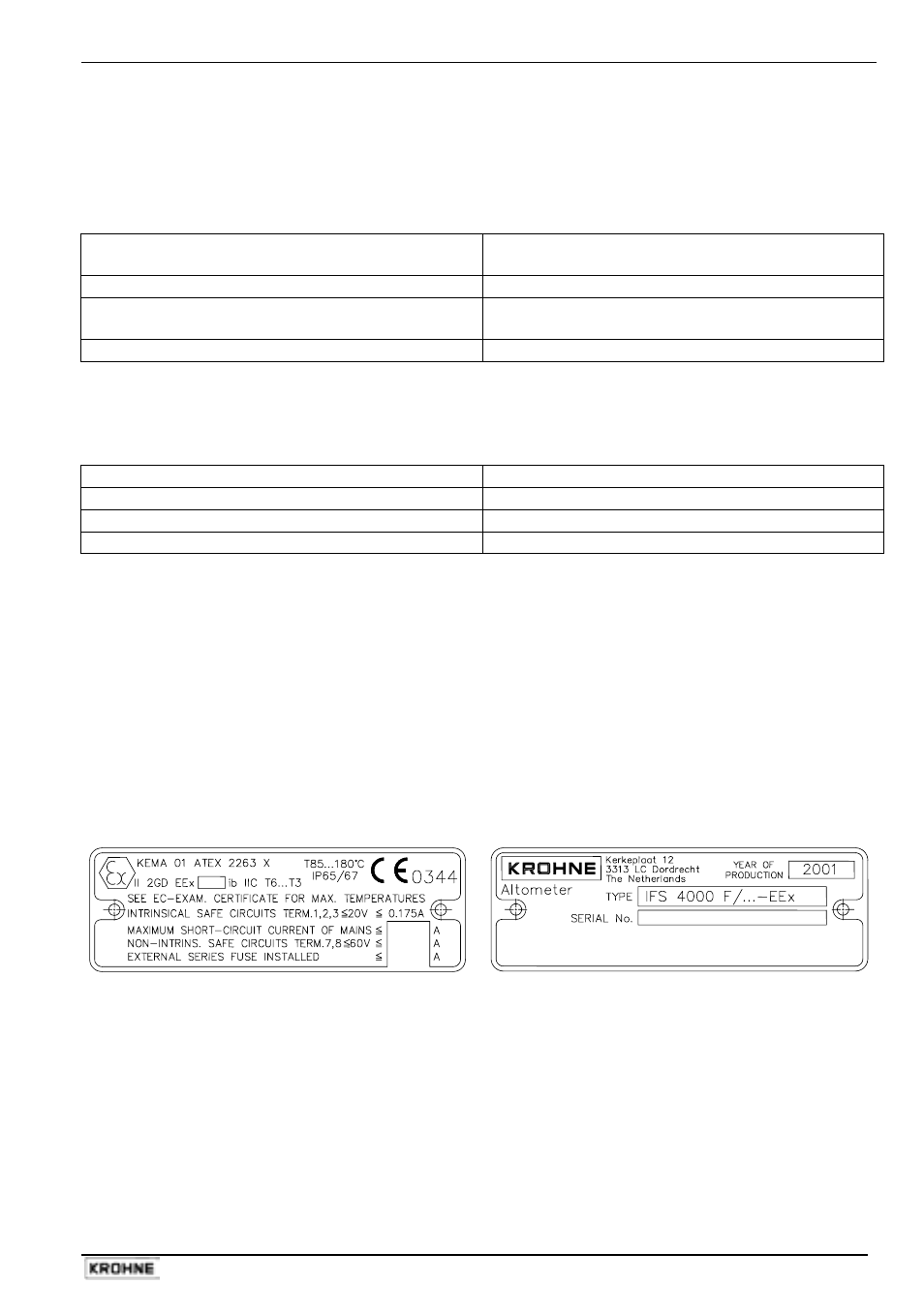
1.1.2 Data plates of ALTOFLUX IFS 4000 F-EEx
Data plate 1
Data plate 2