KROHNE VARIFLUX IFS 6000 F-EEx EN User Manual
Page 11
ALTOFLUX IFS 4000F-EEx, PROFIFLUX IFS 5000F-EEx, VARIFLUX IFS 6000F-EEx
11
2 Electrical
connection
2.1
Primary fuse connection (only for IFS 5000 F-EEx and IFS 6000 F-EEx)
For all meter sizes (DN2.5 up to and including DN100 in case of IFS 5000 F-EEx, DN2.5 up to and
including DN15 in case of IFS 6000 F-EEx) which also have type of protection Encapsulation "m"
according to EN 50028, the associated signal converter may only be connected to a mains supply
with a prospective short-circuit current of maximum 1500 A for the 100…230 Vac mains supplies
or 300 A for 24 Vac/dc mains supplies.
2.2
Fuse protection of field coil circuit
The field coil circuit is protected against over-current by two fuses of type Wickmann TR5 with a
nominal rating of T160mA. These fuses are soldered into the amplifier printed circuit board of the
electronics unit of the associated signal converter (e.g. IFC 090 F/…-EEx).
2.3
Equipotential bonding system
The IFS x000 F-EEx electromagnetic primary head must always be incorporated into the
equipotential bonding system. Therefore the bonding conductor with a cross-sectional area of at
least 4 mm
2
(i.e. AWG 10) must be connected to the external U-clamp terminal M5 that is mounted
to the connecting flange between primary head's housing and junction box.
The U-clamp terminal is made of nickel-plated brass or stainless steel to protect it against corrosion.
Make sure that the core of the bonding wire is properly mounted under the U-clamp and that the
screw is tightly fixed.
2.4
Intermediate junction box ZD-EEx
For safety reasons, standard cables with a rubber or thermoplastic insulation sheath may only be
used up to a continuous operating temperature of 70°C at the cable entry and 80°C at the branching
point of the connecting cables. In case that the temperature at the above mentioned parts exceed
the maximum values, heat-resistant cables must be installed at the IFS x000 F-EEx primary head in
remote design.
Also see the EC-type examination certificate of the primary head.
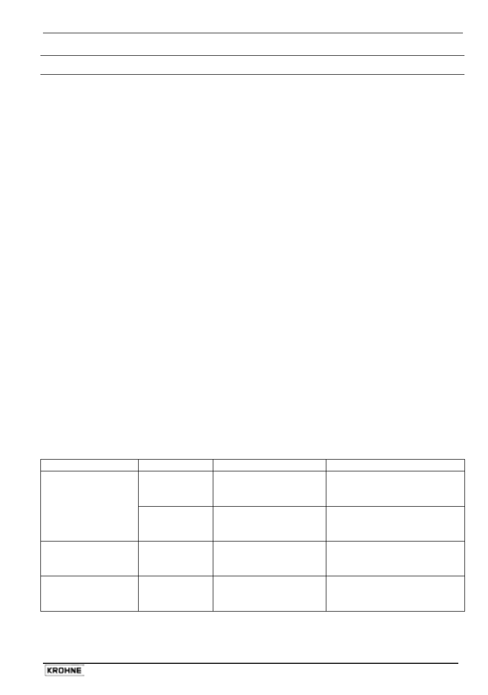
The table below summarizes the conditions for use of heat-resistant cables for the IFS x000 F-EEx
primary head.
Use of heat-resistant cables
Primary head
Meter size
Ambient temperature
Process liquid temperature
DN25 - 150
≤ 40°C
≤ 50°C
≤ 60°C
not required
≥ 155°C
≥ 105°C
IFS 4000 F-EEx
≥ DN200
≤ 40°C
≤ 50°C
≤ 60°C
not required
≥ 145°C
≥ 110°C
IFS 5000 F-EEx
DN2.5 - 100
≤ 40°C
≤ 50°C
≤ 60°C
≥ 165°C
≥ 130°C
≥ 100°C
IFS 6000 F-EEx
DN2.5 - 80
≤ 40°C
≤ 50°C
≤ 60°C
not required
≥ 160°C
≥ 115°C