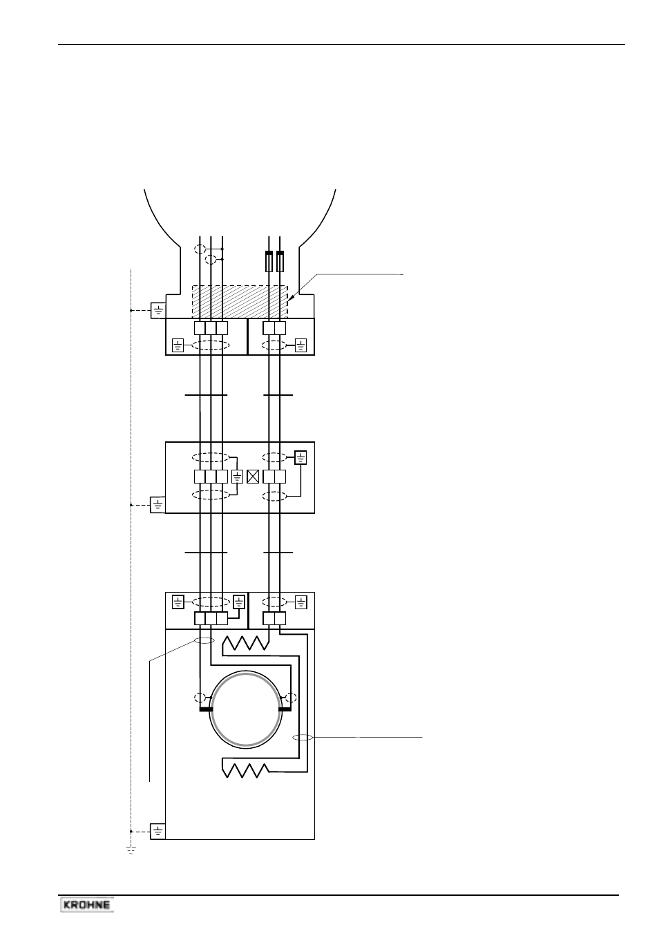
Hazardous locations of zone 1 and 2, E = electrode, Connection diagram 2: use of heat-resistant cables – KROHNE VARIFLUX IFS 6000 F-EEx EN User Manual
Page 15: Flow tube e, Coil e coil, Signal converter, Zd-eex intermediate junction box
ALTOFLUX IFS 4000F-EEx, PROFIFLUX IFS 5000F-EEx, VARIFLUX IFS 6000F-EEx
15
Connection diagram 2: Use of heat-resistant cables
Hazardous locations
of Zone 1 and 2
E
Q
UI
P
O
TE
N
T
IA
L B
O
NDI
N
G
CO
NDU
C
T
O
R
≥
4
mm
2
(O
P
T
IO
N
A
L)
El
ec
tr
ode c
abl
es
-
whi
te/
pi
nk
(P
T
F
E
in
su
la
ted s
hi
el
ded c
opper
)
Field coil wires - green/blue
(PTFE insulated copper)
Flow tube
E
IFS x000 F-EEx
Primary Head type
Coil
E
Coil
E = electrode
3 2 1
7 8
ELECTRONICS COMPARTMENT (always "EEx d")
Intrinsical safe ("ib")
Increased safe ("e")
electrode circuits
field coil circuits
(No. "3", "2", "1")
(No. "7", "8")
Signal Converter
IFC 090 F/…-EEx
Flameproof (EEx d) cable
feed-through LC-2/EEx
B
C
2x fuse
160mA
3 2 1
7 8
3 2 1
7 8
E
D
ZD-EEx
intermediate
junction box
This manual is related to the following products: