KROHNE VARIFLUX IFS 6000 F-EEx EN User Manual
Page 10
10
ALTOFLUX IFS 4000F-EEx, PROFIFLUX IFS 5000F-EEx, VARIFLUX IFS 6000F-EEx
1.4 Block
diagram
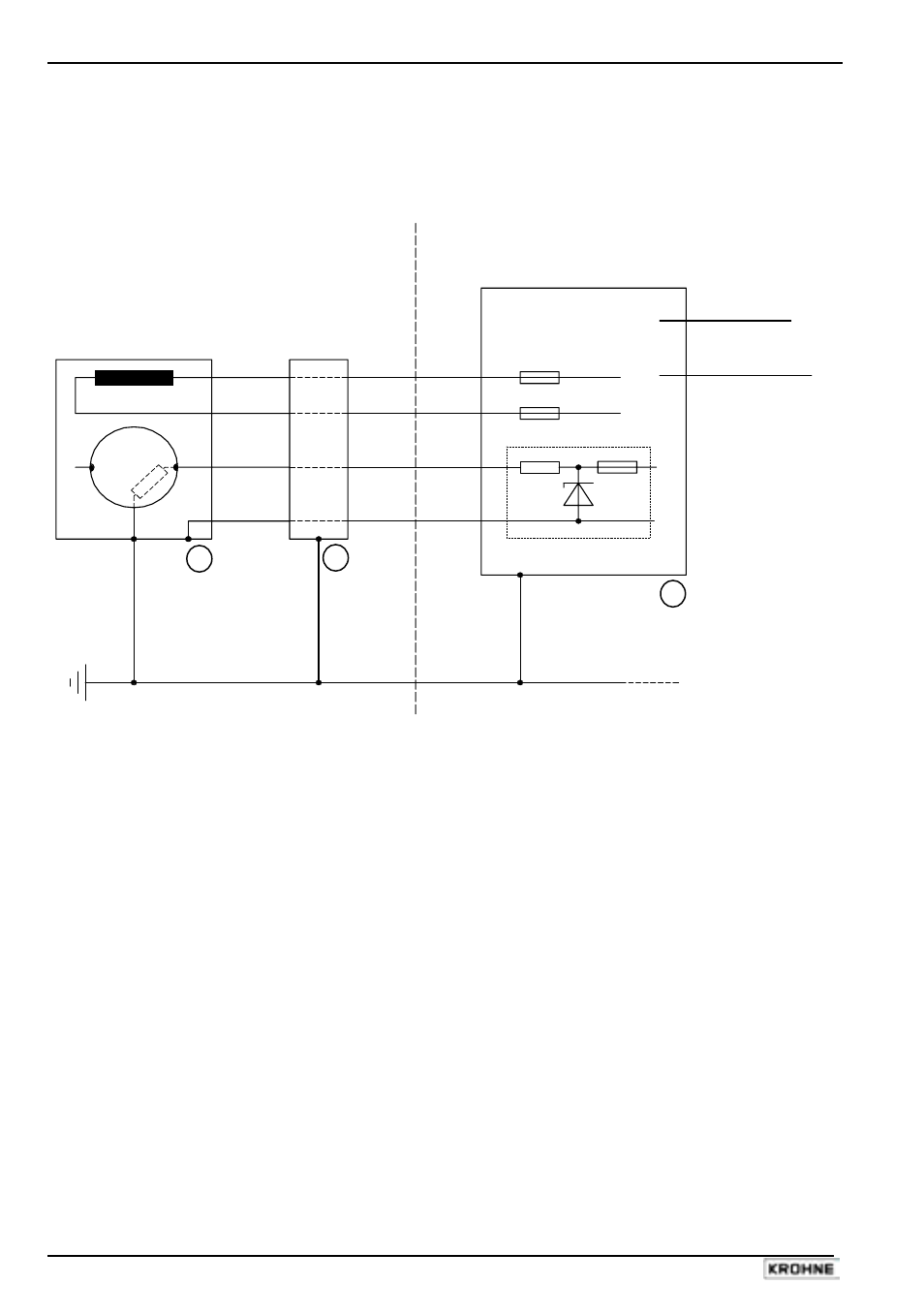
Flowmetering systems designed for use in hazardous areas consist of the following components
resp. instruments.
Block diagram of flowmetering system with IFS x000 F- EEx
Equipotential bonding
Current output
“EEx e”
Frequency output
“EEx e”
B
F
F
M
"EEx e"
2,3
1
"EEx ib"
E
Hazardous area
S
Hazardous area
or safe area
E
3
1
2
7
8
The block diagram above shows the principle of a flowmetering system with IFS x000 F-EEx
primary head, that is suitable for hazardous locations. An explanation of the several shown items
follows:
1. IFS x000 F-EEx primary head.
2. ZD-EEx intermediate junction box. This junction box is used for certain process liquid
temperatures that result in higher temperatures at the cable entries resp. branching point of
the connecting cable(s) than that is allowed for normal cables. The intermediate junction
box is used to keep the heat-resistant cabling as short as possible (max. 5 m), because of
the higher costs.
3. Signal converter unit (e.g. IFC 090 F/…-EEx). The signal converter unit contains the
electronics that drives the primary head. It can be located in a hazardous area, in which
case the IFC 090 F/…-EEx with flameproof housing is used. When installed in a safe (non-
hazardous) area, alternatively to this version the standard non-EEx version can be used. The
standard version is namely also provided with a safety barrier to drive the "EEx ib"
electrodes of the primary head.
Remaining items:
M
E
S
F
B
Measuring tube
Electrode
Magnetic field coil
Field circuit fuse (installed in associated signal converter unit).
Safety barrier with intrinsically safe "ib" outputs.