Hazardous locations of zone 1 and 2, 6 connection diagrams, E = electrode – KROHNE VARIFLUX IFS 6000 F-EEx EN User Manual
Page 14: Connection diagram 1: standard cables, B1 b ⊥ b2 i+ i l n, Signal converter, Flow tube e, Coil e coil
14
ALTOFLUX IFS 4000F-EEx, PROFIFLUX IFS 5000F-EEx, VARIFLUX IFS 6000F-EEx
2.6 Connection
diagrams
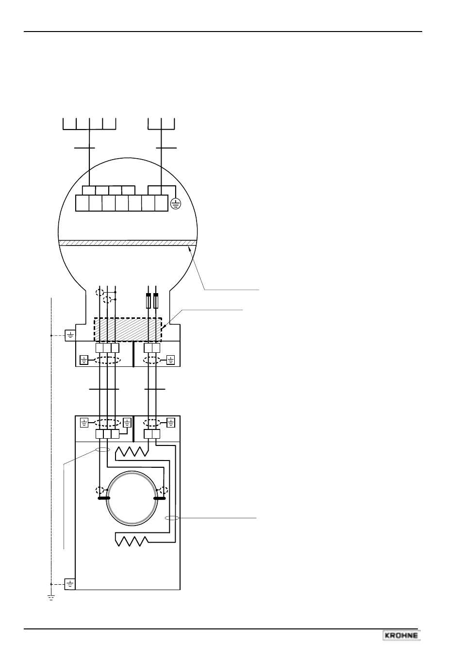
Connection diagram 1: Standard cables
Hazardous locations
of Zone 1 and 2
B1 B
⊥ B2 I+ I L N
BINARY CURRENT
MAINS
OUTPUTS OUTPUT SUPPLY
TERMINAL
COMPARTMENT
Standard "EEx e" (optional "EEx d")
ELECTRONICS COMPARTMENT (always "EEx d")
Intrinsical safe ("ib")
Increased safe ("e")
electrode circuits
field coil circuits
(No. "3", "2", "1")
(No. "7", "8")
Signal Converter
IFC 090 F/…-EEx
PE
FE
L
N
PE
100-230
Vac
SIGNAL IN-/OUTPUTS
L L FE 24
Vac/dc
E
Q
UI
P
O
TE
N
T
IA
L B
O
ND
IN
G
C
O
ND
UC
T
O
R
≥
4
m
m
2
(O
P
TI
O
NA
L)
Flameproof (EEx d) cable
feed-through LC-2/EEx
B
A
E
lec
tr
ode
c
abl
es
-
whi
te
/pi
nk
(P
T
FE
i
ns
ul
at
ed s
hi
el
ded c
op
per
)
Field coil wires - green/blue
(PTFE insulated copper)
Flameproof (EEx d)
terminal feed-through
Flow tube
E
IFS x000 F-EEx
Primary Head
Coil
E
Coil
E = electrode
B
C
2x fuse
160mA
3 2 1
7 8
3 2 1
7 8