Flange connections to din, jis and ansi, 12 11 dimensions and weights, Dn 2.5 - 15 – KROHNE VARIFLUX IFS 6000 EN User Manual
Page 12: Continuation see next page)
12
11 Dimensions and weights
PLEASE NOTE
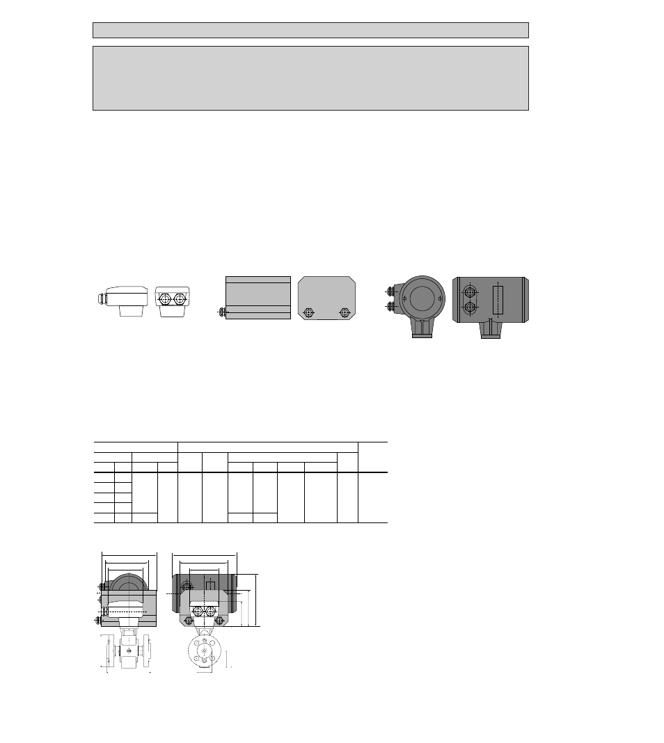
The total dimension for the height is obtained from dimension b (see table) plus the height
of the terminal box or the signal converter, see drawings.
The total weight is made up of the weight of the signal converter (see table)
plus the weight of the terminal box or signal converter, see below.
Terminal box
IFC 010 K and IFC 020 K
signal converter
IFC 090 K signal converter
Weight approx.
0.5 kg (1.1 lb)
Weight approx.
1.6 kg (3.6 lb)
Weight approx.
2.3 kg (5.1 lb)
160 (6.30
,,
)
136 (5.35
,,
)
0
98 (3.86
,,
)
208 (8.19
,,
) Ex: 238 (9.37
,,
)
140 (5.51
,,
)
0
78 (3.07
,,
)
a
0
71 (2.80
,,
)
105 (4.13
,,
)
165 (6.50
,,
)
dia. D
e
b
d
Flange connections to DIN, JIS and ANSI
Flowmeter
Dimensions in mm and (inch)
Approx.
Size/type
Flanges
a
b
max
ØD
d
weight
DIN/JIS ANSI DIN/JIS
ANSI
DIN/PN 40
JIS/20 K
ANSI/150 lb ANSI/300 lb
in kg (lb)
DN
0
2.5
1
/
10
”
DN
0
4
1
/
8
”
DN
0
6
1
/
4
”
DN 10
1/2”
130 (5.12) 142 (5.59) 90 (3.54)
90 (3.54)
88.9 (3.50) 95.2 (3.75)
51 (2.01) 2.6 (5.8)
DN 10
3
/
8
”
DN 15
1
/
2
”
DN 15
95 (3.74)
95 (3.74)
DN 2.5 - 15 /
1
/
10
” -
1
/
2
”
(Continuation see next page)