Installation – KROHNE BM 26 BASIC_ADVANCED Quickstart EN User Manual
Page 6
2
INSTALLATION
6
BM 26 BASIC/ADVANCED
www.krohne.com
10/2012 - 4000346904 - QS BM 26 Basic-Adv R04 en
How to remove the float lock pin (devices with side process connections)
1 Check the measuring chamber for a red sticker next to the bottom side process connection.
i
Sticker text: ATTENTION! Take away transport safety device for float.
2 Remove the adhesive tape around the top and bottom process connections.
3 Remove the plastic protection from the top and bottom process connections.
4 Find the lock pin.
5 Remove the lock pin with a pair of pliers.
How to put the float in the measuring chamber (if it is delivered separately)
• Remove the bottom blind flange or plug (if the basic version has the 1¼¨ drain option).
• Put the top of the float (the float data is on the top part of the float) in the measuring chamber
first.
• Align the gaskets.
• Tighten the nuts on the blind flange to the correct torque (11 Nm in operating conditions,
23.5 Nm in test conditions). The 1¼¨ plug must be tightened in agreement with good
engineering practice.
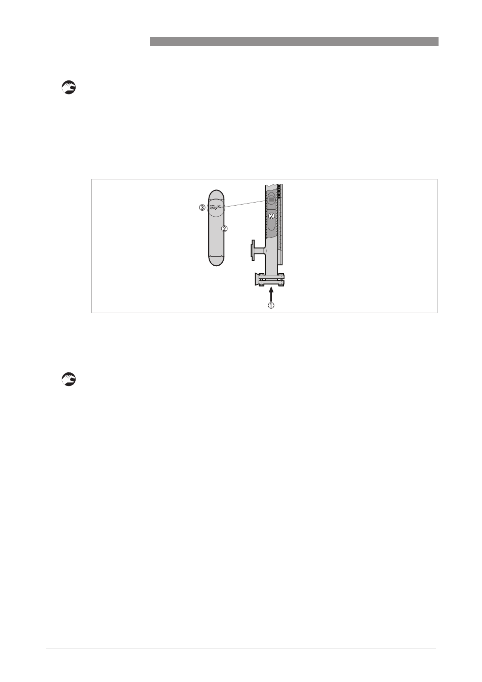
How to put the float in the measuring chamber
Figure 2-4: How to put the float in the measuring chamber (if it is delivered separately)
1 Put the float in here
2 Float
3 The float data (date of manufacture, P
s
/P
t
, float material etc.) must be at the top of the float when you put the float in
the measuring chamber