A.O. Smith VB/VW- 1000 User Manual
Page 35
35
MCB - Ten Position Dipswitch:
Dipswitch configurations are READ ONLY ON POWER UP. These switches are only to be set at the factory or by authorized trained
personnel! Once set the boiler will operate according to the chosen options. If a switch is changed, power must be cycled before the
change will take effect. The status of all dipswitches can be observed on the system status screen on the UIM.
TABLE 9. - MCB/FCB Dipswitches:
Dipswitch Function
Switch Position
Hot Water Boilers
Hydronic Heating Boiler
Switch 1: Selection of the type of boiler application:
On = VB
Off = VW
Switch 2: Trials for ignition:
On = 3
Off = 1
Switch 3: IRI Gas Valve Not Available:
Switch 4: Controlling Probe:
On = Tank (Remote) Off = Inlet
Switch 5: Powered Venter:
On = Yes
Off = No
Switch 6: Low Water Cut Off: (LWCO)
On = Yes
Off = No
Switch 7: Low Gas Pressure
On = Yes
Off = No
Switch 8: Modulation:
On
NOTE: If the unit powers up with the number of stages selected by dip switches exceeding the number of FCBs, the MCB will detect
this condition and go into a hard lockout.
After changing the dipswitches, the power must be cycled off and back on to accept
any changes.
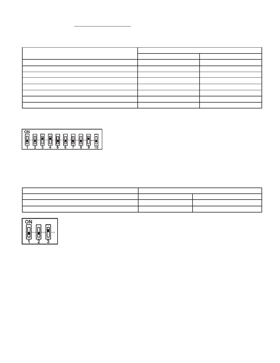
Example of Dipswitch configuration:
VB model, 1ignition trial, not used, tank / remote probe, no power vent, No LWCO,
no low gas pressure, modulation, not used, not used.
MCB - Three position Dipswitch:
This dipswitch is similar to the MCB dipswitches described above, but with only three switches being used: the number of blower speeds
(switch #3), Hi Gas option (switch #2) and a spare (switch #1). Only the blower speed and Hi Gas options are the required selection,
within the MCB, see Figure 17.
TABLE 10.
Dipswitch Function:
Dipswitch Position
Switch 1: Spare:
Switch 2: Hi Gas pressure switch:
On = Yes
Off = No
Switch 3: Number of Blower Speeds:
On = 1 speed,
Off = 2 speed
Example of Dipswitch configuration:
No High Gas, 1 blower speed.