Safety-related characteristics – KROHNE H250 M40 Safety V1 EN User Manual
Page 15
SAFETY-RELATED CHARACTERISTICS
7
15
H250 M40
www.krohne.com
02/2012 - 4000904201 MA H250 M40 SIL R01 en
H250/M40/HT/K*-SK
H250/M40/HT/K*-SK
H250/M40/HT/K*-SK
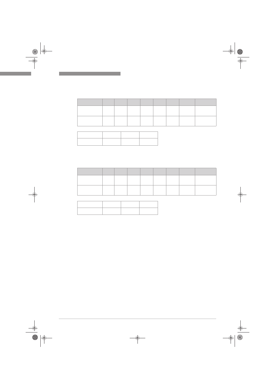
H250/M40/HT/K*-SK with 1 or 2 fail-safe limit switches
fail-safe limit switches
fail-safe limit switches
fail-safe limit switches (MIN/MAX) 1 and screwed
screwed
screwed
screwed
process connections
H250/M40/HT/K*-SK
H250/M40/HT/K*-SK
H250/M40/HT/K*-SK
H250/M40/HT/K*-SK with 1 or 2 standard limit switches
standard limit switches
standard limit switches
standard limit switches (MIN/MAX) 6 and screwed
screwed
screwed
screwed
process connections
λ
SD
λ
SU
λ
DD
λ
DU
SFF 2 DC
D
MTBF
SIL AC 3
Stress profile 2
(low stress)
0 FIT
252 FIT
10 FIT
84 FIT
75%
10%
313 years
SIL2
Stress profile 4
(high stress)
0 FIT
294 FIT
10 FIT
139 FIT
68%
6%
243 years
SIL2
T[Proof] 4
1 year
2 years
5 years
PFD
AVG
5
4.01*E-04
7.66*E-04
1.86*E-03
λ
SD
λ
SU
λ
DD
λ
DU
SFF 2 DC
D
MTBF
SIL AC 3
Stress profile 2
(low stress)
0 FIT
283 FIT
10 FIT
122 FIT
70%
7%
263 years
SIL2
Stress profile 4
(high stress)
0 FIT
325 FIT
10 FIT
177 FIT
65%
5%
212 years
SIL2
T[Proof] 4
1 year
2 years
5 years
PFD
AVG
5
5.83*E-04
1.11*E-03
2.70*E-03
1 The switching contact output is connected to a fail-safe NAMUR amplifier (e.g.
Pepperl+Fuchs KF**-SH-Ex1). The failure rates of the amplifier are not included in the
listed failure rates.
2 The number listed is for reference only. The SFF must be determined for the complete
subsystem.
3 SIL AC (architectural constraints) means that the calculated values are within the range
for hardware architectural contraints for the corresponding SIL level.
4 It is assumed that proof testing is performed with a proof test coverage of 99%.
5 The PFD
AVG
was calculated for profile 2 using the Markov modelling. The results must be
considered in combination with PFD
AVG
values of other devices of the Safety Instrumented
Function (SIF) in order to determine suitability for a specific Safety Integrity Level (SIL)
For SIL1 applications, the PFD
AVG
value needs to be < 10
-1
.
For SIL2 applications, the PFD
AVG
value needs to be < 10
-2
.
6 The switching contact output is connected to a standard NAMUR switching amplifier (e.g.
Pepperl+Fuchs KF**-SR2-Ex*.W). The failure rates of the amplifier are not included in the
listed failure rates.
MA_H250_M40_SIL2_R01_en_904201_PRT.book Page 15 Thursday, March 1, 2012 10:08 AM