Modbus protocol, 7 input registers – KROHNE IFC 050 Converter Modbus EN User Manual
Page 12
6
MODBUS PROTOCOL
12
IFC 050
www.krohne.com
09/2012 - 4002202601 - AD Modbus IFC 050 R01 en
6.7 Input registers
All input registers in the Modbus protocol address range from 30000 to 38998 are mapped into
the range 0 to 8998. All input registers in the Modbus protocol address range from 20000 to
20998 are mapped into the range 9000 to 9998. This is done to give systems with restriction on
the address range access to the device.
Measurement and status values are read only and can be accessed as Modbus "Input Registers".
Cyclic GDC objects are mapped to Modbus Registers.
Function code is 04 (0x04).
Input register 30018 is not used up to now. This is included to fill the gap between the float and
double float values and allows to read the full range of registers.
Also the result of a calibration procedure is accessed by an input register at Modbus Protocol
Address 20000 or 9000. The type are one or more float values. This is depending on the used
function (refer to "Calibration procedures").
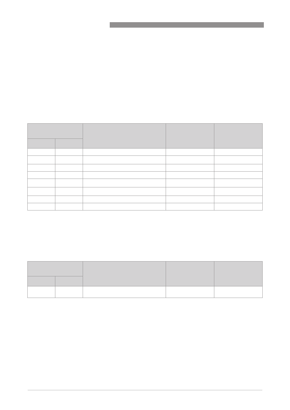
Modbus protocol
address
Description and settings
Type
Number of registers
1st
2nd
30000
0
flow speed
flow speed
flow speed
flow speed [m/s]
float
2
30002
2
volume flow
volume flow
volume flow
volume flow [m
3
/s]
float
2
30004
4
mass flow
mass flow
mass flow
mass flow [kg/s]
float
2
30006
6
Operating time
Operating time
Operating time
Operating time [s]
float
2
30008
8
Counter 1
Counter 1
Counter 1
Counter 1 [m
3
] or [kg]
double float
4
30012
12
Counter 2
Counter 2
Counter 2
Counter 2 [m
3
] or [kg]
double float
4
30016
16
long status sensor
long status sensor
long status sensor
long status sensor
byte [4]
2
30018
18
long status device
long status device
long status device
long status device
byte [4]
2
Modbus protocol
address
Description and settings
Type
Number of registers
1st
2nd
20000
9000
Result of a calibration function
one or more float
values
2 times number of
values