Figure 3. component locations – KEPCO RTW 100W User Manual
Page 2
2
228-1504 REV 11
032111
KEPCO, INC. " 131-38 SANFORD AVENUE " FLUSHING, NY. 11355 U.S.A. " TEL (718) 461-7000 " FAX (718) 767-1102
http://www.kepcopower.com " email: [email protected]
POWER FACTOR:
0.99 typ. at 100 Va-c, 0.92 typ. at 200 Va-c.
STABILIZATION:
Source Effect: (85 to 132Va-c, 170-265 Va-c) 0.1% typ., 0.2% max. (3.3V model:
5mV typ., 10mV max.)
Load Effect: (0% - 100% of rated output current) 0.2% typ., 0.4% max. (3.3V
model: 10mV typ., 20mV max.)
Temperature effect: (-10 to 71°C) 0.5% typ., 1.0% max.
Combined effect (source, load, temperature): 0.9% typ., 1.8% max.
Time effect (drift): (1/2 to 8 hr. at 25°C) 0.2% typ., 0.5% max.
TRANSIENT RECOVERY:
A step load change from 50% to 100% of rated output
current in 50 microseconds or more, produces no more than 4% output voltage excur-
sion (3.3V model: 200mV max.). Recovery time is 1ms maximum.
ACCEPTABLE LOAD CAPACITANCE:
10,000
µ
F max (start-up time is affected)
OUTPUT HOLDING TIME:
Upon input interruption the output is maintained for 35
milliseconds typical (20 ms min.).
START UP TIME:
400ms typ., 500ms max. at 100 Va-c; 200ms typ., 300ms max.,
at 240 Va-c. Between 0 and -20° C output may take 3 seconds to stabilize.
OVERVOLTAGE PROTECTION:
Fixed, factory set. See Table 1. The overvoltage
circuit is set by Zener diode clamp, latching will occur.
OVERCURRENT:
Hiccup type, output voltage returns to rated level upon removal
of cause of malfunction.
OPERATING TEMPERATURE:
-10 to 71°C (start up -20 to -10°C). See the derat-
ing, Figure 1 or 2. Do not allow the power supply to become dust covered because that
will decrease the cooling efficiency of the unit and cause insulation to deteriorate.
STORAGE TEMPERATURE:
-30°C to + 75°C.
COOLING:
Natural convection.
ORIENTATION:
Vertical or horizontal (see Figure 5).
HUMIDITY:
Operating: 10% to 95% relative humidity, storage:10% to 95% relative
humidity; noncondensing, wet bulb temperature < or = 35°C.
WITHSTANDING VOLTAGE
(at 15 to 35°C ambient, 10 to 85% relative humidity):
Between input and output terminals, 3.0 KV a-c for 1 minute, cutout current 10 ma.
Between input terminals and ground, 2.0 KV a-c for 1 minute, cutout current 10 ma.
Between output terminals and ground, 500V a-c for 1 minute, cutout current 20 ma.
INSULATION RESISTANCE:
Between input and output, input and ground, output
and ground, ±RC terminals and output, ±RC terminals and input: 100 megohms
minimum (500V d-c, 15 to 35°C ambient, 10 to 85% relative humidity).
VIBRATION:
Three axes, one hour each, sweep time 10 min:, nonoperating
5-10 Hz., 10 mm amplitude.
10-200 Hz., 2G (19.6m/S
2
).
SHOCK:
Three axes, 20G (196m/S
2
) when installed per Figure 5, method A, 60G
(588m/S
2
) when installed per Figure 5, method B or C, 11ms ±5 msec pulse dura-
tion, three shocks each axis, nonoperating, 1/2 sine pulse.
EMC - EMISSIONS:
Radiated Noise 30MHZ to 1GHz: FCC Class B, VCCI-B, EN55011-B, EN55022-B
Conducted Noise 0.15MHz to 30MHz: FCC Class B, VCCI-B, EN55011-B,
EN55022-B
Input Harmonics (on AC Mains) 0 to 2KHZ: EN 61000-3-2.
EMC - IMMUNITY:
ESD: EN 61000-4-2 Level 4, Normal operation.
Radiated Field Noise: EN 61000-4-3 Level 3, Normal operation.
Electrical Fast Transient/Burst (EFT): EN 61000-4-4 Level 3, Normal operation.
Surge: EN 61000-4-5 Level 4, no damage.
Conducted Noise: EN 61000-4-6 Level 3, Normal operation.
Power Frequency Magnetic Field: EN 61000-4-8 Level 4, Normal operation.
Voltage Dips, Short Interruptions, Voltage Variation: EN 61000-4-11, Normal
operation.
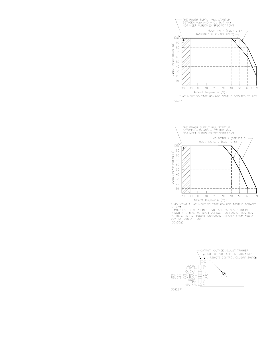
FIGURE 1. OUTPUT POWER VS.
TEMPERATURE,
K MODELS (WITHOUT COVER)
FIGURE 2. OUTPUT POWER VS.
TEMPERATURE
KC MODELS (WITH COVER)
FIGURE 3. COMPONENT LOCATIONS
SAFETY:
All units designed to meet EN 60950:2001 Assistance for DEN-AN. U.S. UL 60950 First Edition.; Canada: CSA-22.2 No. 60950-1.
(ambient temp. 50°C). RTW 100W units are CE marked per the Low Voltage Directive (LVD), EN60950 73/23/EEC AND 93/68/EEC. [The
standards do not apply with DC input operation.]
WEIGHT:
13.4 oz. (380 grams) max
WARRANTY:
One year.