Weight, Warranty, Iii — installation – KEPCO RTW 150W User Manual
Page 3: Mounting the power supply, Connections, Local/remote sensing, Iv — operation, Remote on off, Remote voltage programming, Series operation
KEPCO, INC. " 131-38 SANFORD AVENUE " FLUSHING, NY. 11355 U.S.A. " TEL (718) 461-7000 " FAX (718) 767-1102
http://www.kepcopower.com " email: [email protected]
032111
228-1559 REV 7
3
WEIGHT:
K models (without cover): 1.15 lbs. (520 grams) max.; KC models (with cover): 1.32 lbs. (600 grams) max.
WARRANTY:
One year.
III — INSTALLATION
MOUNTING THE POWER SUPPLY:
Refer to Figures 5 and 6. The unit may be mounted on one mounting surface.
Note the restric-
tions for maximum penetration of mounting screws. The air temperature surrounding the power supply must not exceed the ambient values
given in the graph in Figure 1.
CONNECTIONS:
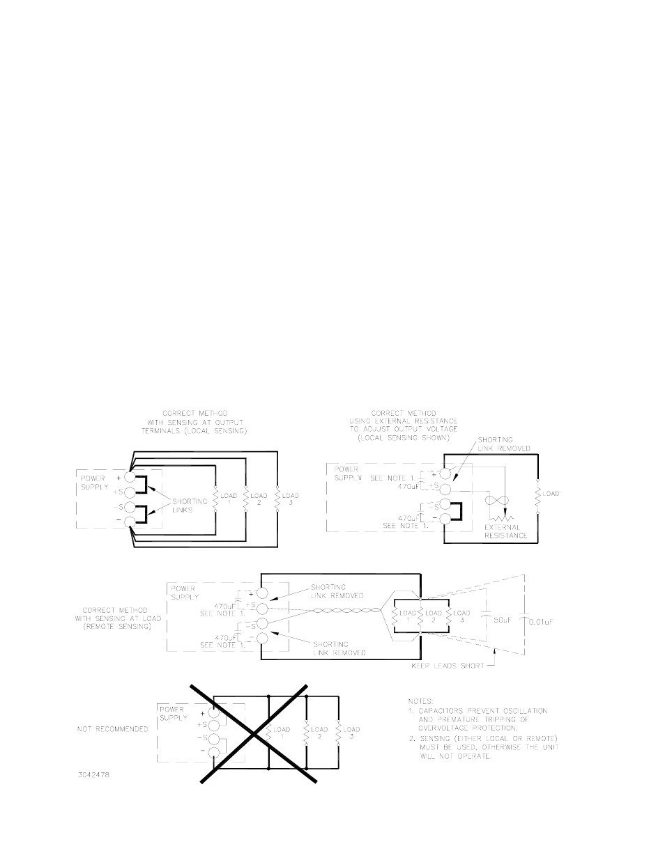
Connect the load to the power supply as shown in Figure 4A, B, or C. The unit is shipped with shorting links in place for
Local sensing. The AC input power is applied via the terminal block. Make sure to connect the AC input Neutral, Line and Ground wires to
the respective terminals of the terminal block (see Figure 3). Sensing (either Local or Remote) MUST be used.
LOCAL/REMOTE SENSING:
Figure 4 shows proper connection of multiple loads using either remote or local sensing. If local or remote
sensing is not configured, the unit will not work properly. The unit is shipped with shorting links in place for Local sensing. For remote
sensing, remove the shorting links and connect the +S and –S terminals to the load. Remote sensing compensation is up to 0.4V per load
wire (0.15V for RTW 3.3-35K, 0.25V for RTW 5-30K). Load wire length should not be more than 16.4ft. (5m). Transient recovery specs may
not be met when remote sensing is used. To prevent oscillations and premature tripping of overvoltage protection, install one electrolytic (not
tantalum) capacitor (470mF min) between +S and + and one between – and –S terminals.
IV — OPERATION
When output voltage is available, the green LED is on. The Output Voltage Adjust trimmer (see Figure 3) allows adjustment of the output
voltage within the range specified in Table 1.
REMOTE ON OFF:
Use ±RC terminals to set output on or off after setting the Remote On/Off switch to Y (see Figure 3). Output OFF
requires no voltage, or short circuit, or 0 to 0.8V d-c across ±RC terminals; Output ON requires 4.5 to 12.5V d-c (or 12.5 to 24.5V d-c through
1.5K Ohms) across ±RC terminals. ±RC terminals are isolated from AC input and DC output terminals.
REMOTE VOLTAGE PROGRAMMING:
In addition to the integral trimmer, output voltage can be also be adjusted via an external vari-
able resistance (see Figure 4B). The variable resistance specified in Table 1 must be substituted for the shorting link between + and +S ter-
minals. Note that load effect for RTW 150W is increased using this technique, and may exceed values listed above under STABILIZATION.
SERIES OPERATION:
When a number of power supplies are operating in series, the current rating is to be limited to the rating of the
power supply with the lowest rating. A diode (Vr>2 Vo, If>2Io, Vf<< low) must be connected to the power supply output terminals to protect
the unit from reverse voltage.
FIGURE 4. LOAD CONNECTIONS
Σ
B
A
C
D