V — operation, Figure 2. component locations, Remote voltage programming – KEPCO RKW 100W Series Operator Manual User Manual
Page 4: Series operation, Parallel operation, Figure 3. load connections, V de
4
228-1445 REV 9
082610
KEPCO, INC. 131-38 SANFORD AVENUE FLUSHING, NY. 11355 U.S.A. TEL (718) 461-7000 FAX (718) 767-1102
http://www.kepcopower.com email: [email protected]
V — OPERATION
When output voltage is available, the green LED is on.
The Output Voltage Adjust trimmer (see Figure 2) allows
adjustment of the output voltage within the range specified
in Table 1.
FIGURE 2. COMPONENT LOCATIONS
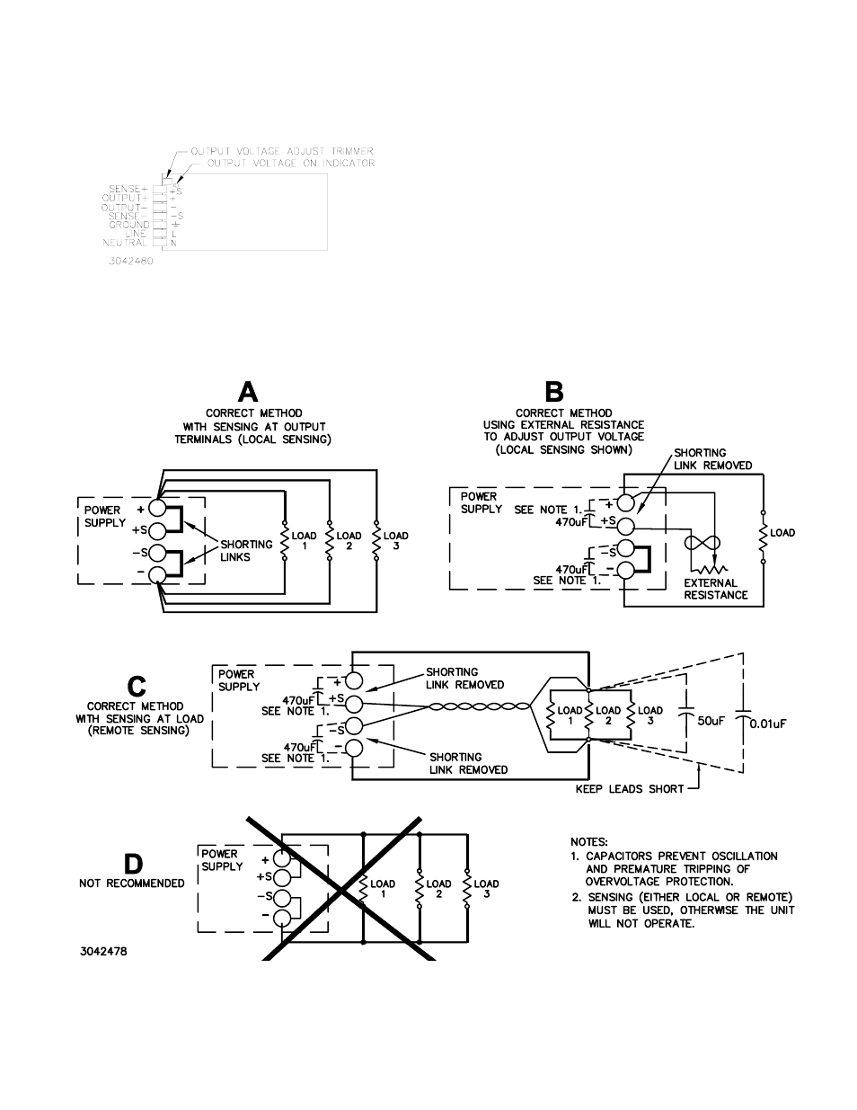
REMOTE VOLTAGE PROGRAMMING: In addition
to the integral trimmer, output voltage can be also be
adjusted via an external variable resistance (see Figure
3B). The variable resistance specified in Table 1 must be
substituted for the shorting link between + and +S termi-
nals. Note that load effect for RKW 100W is increased
using this technique, and may exceed values listed above
under STABILIZATION.
SERIES OPERATION: When a number of power sup-
plies are operating in series, the current rating is to be lim-
ited to the rating of the power supply with the lowest
rating. A diode (Vr>2 Vo, If>2Io, Vf<< low) must be con-
nected to the power supply output terminals to protect the
unit from reverse voltage.
PARALLEL OPERATION: Identical units may be oper-
ated in parallel for increased current capability. Use either
local or remote sensing for all supplies in the parallel
group.
FIGURE 3. LOAD CONNECTIONS
Σ