KEPCO RA 40 User Manual
Ra 40, Kepco, Enclosures and hardware systems
©2002, KEPCO, INC
1
Data subject to change without notice
228-0845 REV 3
I N S T R U C T I O N M A N U A L
RA 40
KEPCO
KEPCO, INC. " 131-38 SANFORD AVENUE " FLUSHING, NY. 11352 U.S.A. " TEL (718) 461-7000 " FAX (718) 767-1102
http://www.kepcopower.com " email: [email protected]
An ISO 9001 Company.
RACK SYSTEM
ENCLOSURES AND
HARDWARE SYSTEMS
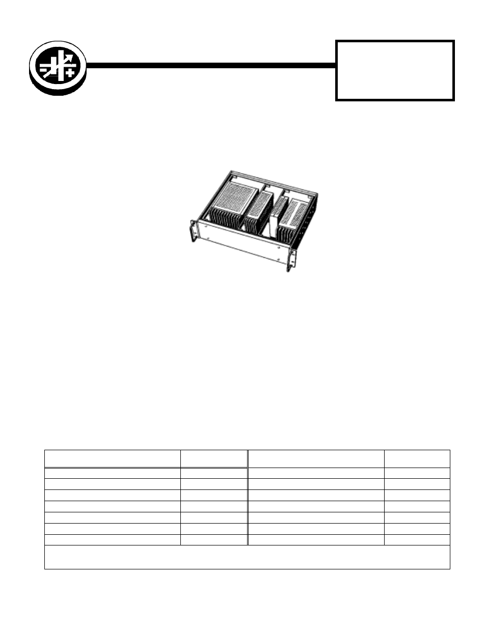
DESCRIPTION. The Kepco Model RA 40 Rack Adapter is designed for the installation of Kepco Switching Power Sup-
plies into a standard 19-inch Rack. In order to accommodate the various models, mounting brackets (not supplied with
the RA 40 rack adapter) are required. The mounting brackets are first attached to the power supplies, which are then
attached to the front and rear rails of the model RA 40 Rack Adapter.
FIGURE 1. KEPCO MODEL RA 40 RACK ADAPTER SHOWN WITH POWER SUPPLIES MOUNTED
INSTALLATION The Kepco Model RA 40 Rack Adapter may be bolted permanently into a standard 19-inch rack. It can
be placed onto a rack-shelf, or it may be installed with slides. The front flanges are drilled for standard (2-1/4 inch)
mounting hole distances. The sides of the Model RA 40 Rack Adapter are drilled for “Jonathan” slides (Refer to Figure
2, Mechanical Outline Drawing).
CAUTION: Since many Kepco Switching Power Supplies are convection cooled devices, sufficient airflow
around the installed power supplies and around the rack adapter must be provided (1/4 in. mini-
mum). Ambient temperature checks on the completed installation should be compared with the
specified ambient temperature ratings of the power supplies, generally 50° C without derating, up
to 70° C with output current derating (see power supply instruction manual). Heatsink or case tem-
peratures on the installed power supplies must not exceed specified limits.
First remove the front and rear covers of the RA 40 rack adapter, then install the power supplies by using applicable
mounting bracket (Table 1). Mounting hardware and installation instructions are provided with the mounting brackets.
TABLE 1. MOUNTING BRACKETS REQUIRED TO INSTALL POWER SUPPLIES IN RACK ADAPTER
POWER SUPPLY MODELS
MOUNTING BRACKET
MODEL NO.
POWER SUPPLY MODELS
MOUNTING BRACKET
MODEL NO.
ERD (30W, 60W, 150W)
RAB 39-40ERD
RAX (50W, 100W, 175W, 300W)
RAB 39-40RAX
ERX (30W, 60W, 120W)
RAB 39-40X
RAX (1500W)
RAB 40-RCW1500
FAW (50W, 100W, 150W)
RAB 39-40FAW
RCW (350W, 750W)
RAB 39-40RCW
FCP (3W, 10W)
RAB 39-40FMP
RCW (1500W)
RAB 40-RCW1500
FMP (3W, 10W)
RAB 39-40FMP
RKW (300W)
RAB 39-40RKW3
KRW (350KV, 351KV, 352KV) *
RAB 39-40MRW
RKW (30W, 50W, 100W, 150W, 600W)
RAB 39-40RKW6
MRW (150/151KV **, 160/161KV ***, 170/171KV ***)
RAB 39-40MRW
RKW (1500W)
RAB 40-RKW1500
*
Series KRW requires case CA 29 (supplied separately) for mounting in RA 39 or RA 40 rack adapters.
** Series MRW 150/151KV requires case CA 19 (supplied separately) for mounting in RA 39 or RA 40 rack adapters.
*** Series MRW 160/161KV and MRW 170/171KV require case CA 20 (supplied separately) for mounting in RA 39 or RA 40 rack adapters.