Figure 1. derating plot, Iii — installation – KEPCO MTW 15 User Manual
Page 2
2
228-1548 REV 2
031908
KEPCO, INC. " 131-38 SANFORD AVENUE " FLUSHING, NY. 11355 U.S.A. " TEL (718) 461-7000 " FAX (718) 767-1102
http://www.kepcopower.com " email: [email protected]
INPUT CURRENT:
(maximum load at 25°C with nominal output voltage):
0.42A typ. (100 Va-c input, 100% load); 0.25A typ. (240 Va-c input, 100% load)
INPUT PROTECTION AND SOFT START:
A thermistor circuit reduces start-up surge. Units are protected against shorts by an input
fuse. Fuse value 2A, 250V.
INPUT SURGE:
First surge only, not including current flow into EMI filter.
25A typ. (100 V a-c, 100% load, 25°C cold start); 50A typ. (240 Va-c, 100% load, 25°C cold start)
LEAKAGE CURRENT:
0.75mA max, 0.2mA typ at 100V a-c (60Hz single pole switching) in conformance to DENAN .
0.75mA max, 0.3mA typ at 240V d-c (60Hz single pole switching in conformance to UL 60950/IEC 60950-1)
POWER FACTOR:
0.55 typ. at 100 Va-c, 0.45 typ. at 240 Va-c
TRANSIENT RECOVERY:
A step load change from 50% to 100% of rated load in 50 microseconds or more, produces no more than
4% output voltage excursion. Temperature range from -10 to 60°C.
OUTPUT HOLDING TIME:
Upon input interruption the output is maintained for 150 milliseconds typical with 240 Va-c input voltage,
and for 20 milliseconds typical with 100 Va-c input voltage. The condition for output load is 100%.
START UP TIME:
100mS max. (+5V, ±12V) at 100 Va-c, Output voltage may not rise with constant current load. .
OVERVOLTAGE PROTECTION:
Fixed, factory set. See Table 1. The overvoltage circuit is set by Zener diode clamp.
OVERCURRENT:
Hold back method, output voltage returns to rated level upon removal of cause (long term overcurrent could damage
unit)
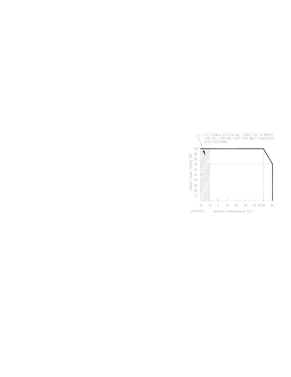
OPERATING TEMPERATURE:
-10 to 60°C (start up -20 to -10°C). See the derating
plot, Figure 1. Do not allow the power supply to become dust covered because that will
decrease the cooling efficiency of the unit and cause insulation to deteriorate.
STORAGE TEMPERATURE:
-30°C to + 75°C.
COOLING:
Natural convection
ORIENTATION:
Horizontal (see Figure 2).
HUMIDITY:
10% to 90% relative humidity, operating and storage, noncondensing,
wet bulb temperature
≤
35°C
WITHSTANDING VOLTAGE:
(at 5 to 35°C ambient, 45 to 85% relative humidity, cutout current 10 ma):
Between input and output terminals, 3.0 KV a-c for 1 minute.
Between input and chassis, 2000V a-c for 1 minute.
Between output terminals and chassis, 500V a-c for 1 minute.
INSULATION RESISTANCE:
(500V d-c, 5 to 35°C ambient, 45 to 85% relative
humidity) Between input and output, input and chassis, and output and
chassis:100 megohms minimum.
VIBRATION:
Three axes, one hour each, sweep time 10 min:, nonoperating
5-10 Hz., 10 mm amplitude;10-200 Hz., 2G (19.6m/s
2
) acceleration
SHOCK:
Three axes, 60G (588m/s
2
), 11 ms ±5msec pulse duration, three shocks each
axis, nonoperating, 1/2 sine pulse
SAFETY:
Meets UL 60950-1.c-UL and TÜV Rheinland EN60950-1 (ambient temp. 50°C max,). Meets creepage and clearance require-
ments of DENAN Appendix 8 (at 100V a-c only). MTW 15W units are CE marked per the Low Voltage Directive (LVD), EN60950. [The
standards do not apply with DC input operation]
EMC - EMISSIONS:
Conducted Noise 0.15MHz to 30MHz: FCC Class B, VCCI-B, EN55011-B, EN55022-B
EMC - IMMUNITY:
ESD: EN 61000-4-2 Level 4, Normal operation.
Radiated Field Noise: EN 61000-4-3 Level 3, Normal operation.
Electrical Fast Transient/Burst (EFT): EN 61000-4-4 Level 3, Normal operation.
Surge: EN 61000-4-5 Level 4, no damage.
Conducted Noise: EN 61000-4-6 Level 3, Normal operation.
Power Frequency Magnetic Field: EN 61000-4-8 Level 4, Normal operation.
Voltage Dips, Short Interruptions, Voltage Variation: EN 61000-4-11, Normal operation.
ELECTROLYTIC CAPACITOR:
Life expectancy: 10,000 hours min. (ambient temp. 50°C)
WARRANTY:
One year.
III — INSTALLATION
MOUNTING THE POWER SUPPLY:
Refer to Figures 2, 3 and 4. The unit may be mounted on one mounting surface. The air sur-
rounding the power supply must not exceed the ambient temperature values given in the graph in Figure 1.
FIGURE 1. DERATING PLOT