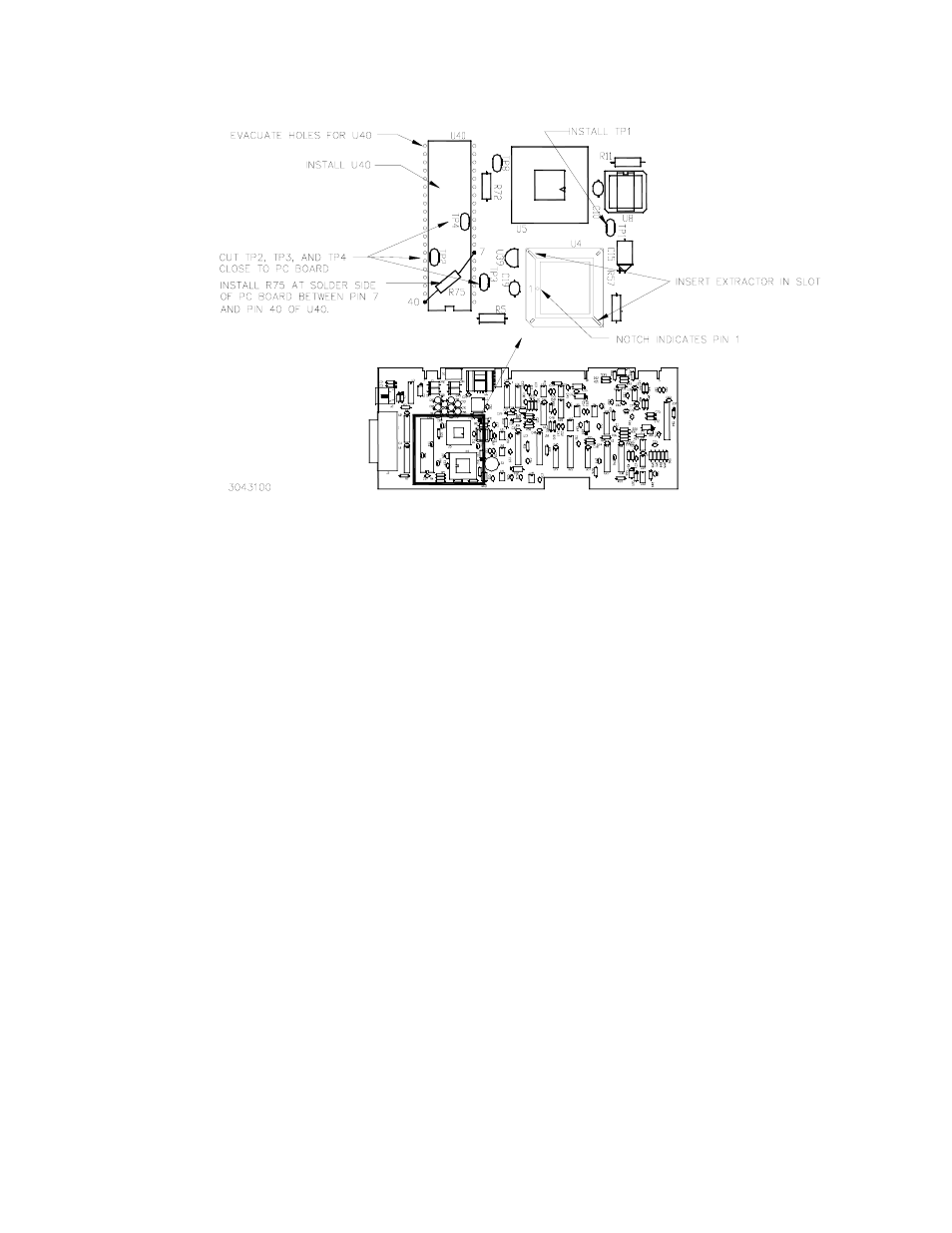
Figure 1. component location – KEPCO KIT 219-0515, BIT 4886 Version 2.0 Firmware Upgrade Kit User Manual
Page 2
2
228-1577 REV 1
082106
KEPCO, INC. " 131-38 SANFORD AVENUE " FLUSHING, NY. 11352 U.S.A. " TEL (718) 461-7000 " FAX (718) 767-1102
http://www.kepcopower.com " email: [email protected]
FIGURE 1. COMPONENT LOCATION
4. Cut test points TP2, TP3, and TP4 (see Figure 1) as close to the PC board as possible. Save test points
5. Evacuate the holes shown in Figure 1 for U40.
6. Install Bus Interface controller chip U40 from kit as shown in Figure 1 and solder in place.
7. Install one test point removed in step 4 in position TP1 as shown in Figure 1 and solder in place.
8. Install resistor R75 from kit on solder side of PC board as shown in Figure 1 and solder in place.
9. Locate the small depression or notch in the PROM U4 as shown in Figure 1. This is pin 1 of the PROM.
CAUTION: FAILURE TO USE THE ESD WRIST STRAP MAY DAMAGE THE PROM!
10. Connect the wrist strap to the chassis of the BOP using the peel and stick tape. Place the strap on your
wrist as indicated by the instructions for the wrist strap.
11. Touch the IC tube to the chassis of the BOP. Open one end.
12. Use the extractor and insert the hook, first into one slot and then the other, and gently pry out PROM U4.
Place the PROM in the tube and close the tube.
13. Open the other end of the IC tube and remove the replacement PROM U4 from the tube.
14. Insert the PROM into the socket, insuring pin one is as shown in Figure 1.
15. Reclose the IC tube. Remove wrist strap and disconnect it from the BOP.
16. Reinstall the BIT 4886 Card in the BOP by referring to the BIT 4886 Technical Manual (downloadable at
www.kepcopower.com/support), PAR. 2.3, steps 9 through 13 and steps 16 through 18.
17. Reconnect power cord and turn on the BOP. Verify the unit beeps and initializes normally.