Figure 3. installation of r206 – KEPCO Kit 219-0425, Pass Assembly A3 Replacement for ATE 325-0.8 User Manual
Page 3
052804
228-1482 REV 1
3
KEPCO, INC. " 131-38 SANFORD AVENUE " FLUSHING, NY. 11352 U.S.A. " TEL (718) 461-7000 " FAX (718) 767-1102
http://www.kepcopower.com " email: [email protected]
8. At rear panel, remove R205 from terminal block TB201 (see Figure 1). Install sleeving provided over leads of new
R205 and install across terminals 4 and 9 of TB201 at rear panel.
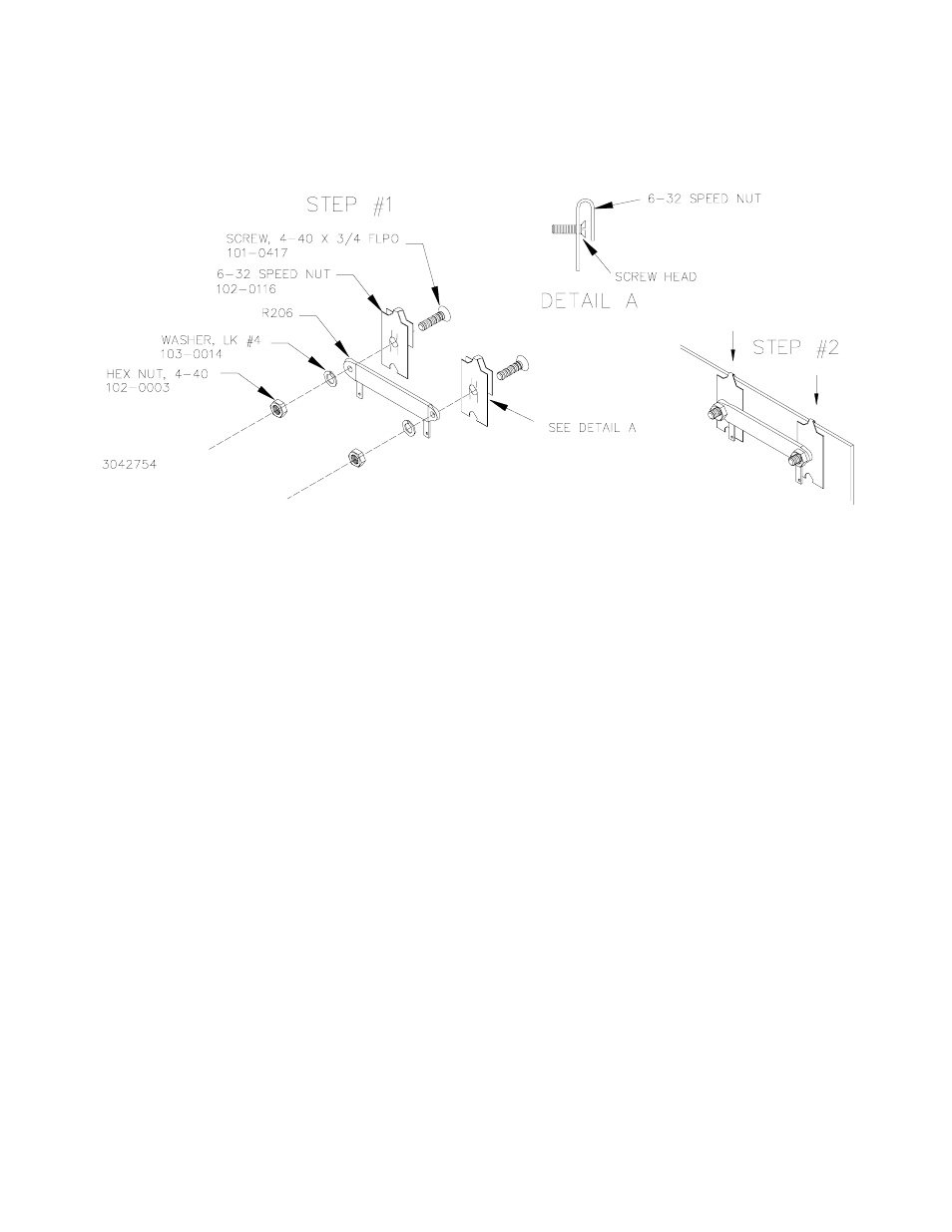
9. Referring to Figure 3, step 1, assemble new R206 onto two speed nuts and secure using screws, washers and nuts
provided in this kit (see Figure 3). Then press clip-on speed nuts (with R206 assembled) onto the bracket as shown in
step 2.
FIGURE 3. INSTALLATION OF R206
10. Refer to Figure 4 and disconnect orange wire (1-O) from connector J204 pin 4 and connect to J205 pin 3.
11. Route wire #44 (Green) along harness and connect one end to connector J204 pin 4, and the other end to connector
J205 pin 4.
12. Disconnect red wire (2-R) from connector J204 pin 1. Route wire #45 (Red) along harness and connect one end to
connector J204 pin 1. Connect the other end, together with red wire previously disconnected from J204 pin 1, to R206
terminal 1.
13. Connect one end of jumper (wire #18) to R206, terminal 2, and the other end to R203, terminal C1.
14. Route wire #24, 25 along harness and plug connector into A3 pass assembly at one end. At the other end connect
wire #24 (White-Yellow) to J202 pin 17 and wire #25 (White-Purple) to J202 pin 19.
15. Reattach connectors J201, J202 and J203 on A1 Assembly (see Figure 1), then secure PCB to chassis using four
screws previously removed.
16. Reconnect connectors J204 and J205 on A3 assembly.
17. Secure wires to harness using cable ties as needed.
18. If removed, reattach ground strap to cover using nut, flat washer and lockwasher previously removed. Reinstall cover
using 10 screws previously removed.