Figure 1. bus bar link removal/installation – KEPCO Kit 219-0429, Bus Bar Links Kit (for RA 59) User Manual
Page 2
2
228-1461
102802
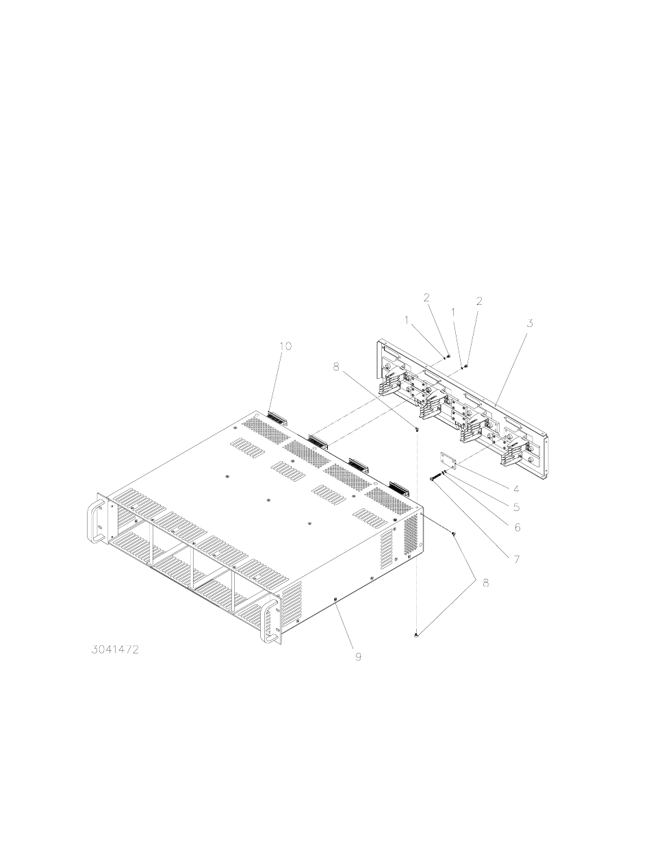
FIGURE 1. BUS BAR LINK REMOVAL/INSTALLATION
KEY TO Figure 1:
1.
Lockwasher, Internal tooth, #4 - P/N 103-0014 (2 per I/O connector)
2.
Screw (2 per I/O connector - part of Jackpost Kit P/N 108-0203
3.
Backplate Assembly
4.
** Bus Bar Link - P/N 172-0513 (2)
5.
** Flat washer, #6 - P/N 103-0100 (4 per bus bar link)
6.
** Lockwasher, Split, #6 - P/N 103-0066 (4 per bus bar link)
7.
** Screw, 6-32 x 1/2” PHPH, self-forming, P/N101-0457 (4 per bus bar link)
8.
Screw, 6-32 x 5/16” FHPO - P/N 101-0408 (12)
9.
Chassis
10. I/O Connector Assembly
** Items included in Kit, P/N 219-0429.
NOTE: Quantities are indicated in parentheses.
See also other documents in the category KEPCO Power suppliers:
- ABC-DM SERIES (96 pages)
- ATE (all models) QUICK START GUIDE (8 pages)
- SN 488-D (94 pages)
- SN 488-D (14 pages)
- SN 488-D (16 pages)
- BHK-MG 200W (Full Rack) Series (152 pages)
- BHK-MG 40W (Half Rack) Series (148 pages)
- BIT 232 (72 pages)
- BIT 4882 (56 pages)
- BIT 4886 Quick Start Guide (4 pages)
- BIT 4886 Operator Manual (92 pages)
- BOP 100W, 200W, 400W (M, D) Quick Start Guide (8 pages)
- BOP 20-5ML Modification Sheet (1 page)
- BOP 20-10MC Modification Sheet (2 pages)
- BOP 36-6MC Modification Sheet (2 pages)
- BOP 100-2MC Modification Sheet (2 pages)
- BOP 50-4MC Modification Sheet (2 pages)
- BOP 100-2ML Modification Sheet (2 pages)
- BOP 72-3ML Modification Sheet (2 pages)
- BOP 50-4ML Modification Sheet (2 pages)
- BOP 36-6ML Modification Sheet (2 pages)
- BOP 20-10ML Modification Sheet (2 pages)
- BOP 72-6MC Modification Sheet (2 pages)
- BOP 36-12MC Modification Sheet (2 pages)
- BOP 20-20MC Modification Sheet (2 pages)
- BOP 100-4ML Modification Sheet (2 pages)
- BOP 72-6ML Modification Sheet (2 pages)
- BOP 50-8ML Modification Sheet (2 pages)
- BOP 36-12ML Modification Sheet (2 pages)
- BOP 20-20ML Modification Sheet (2 pages)
- BOP 1KW-MG Quick Start Guide (16 pages)
- BOP 1KW-MG Quick Reference Guide (2 pages)
- BOP 1KW-MG Operator Manual, Firmware Ver.4.12 and higher (196 pages)
- BOP 1KW-MG Operator Manual, Firmware Ver.4.08 to 4.11 (194 pages)
- BOP 1KW-MG Operator Manual, Firmware Ver.3.05 to 4.07 (194 pages)
- BOP 1KW-MG Operator Manual, Firmware Ver.2.48 to 3.04 (188 pages)
- BOP 1KW-MG Operator Manual, Firmware Ver.2.38 to 2.47 (188 pages)
- BOP 1KW-MG Operator Manual, Firmware Ver.2.01 to 2.37 (176 pages)
- BOP 1KW as Solar Device Tester Quick Start Guide (3 pages)
- BOP-GL 1KW Quick Start Guide (16 pages)
- BOP-GL 1KW Operator Manual Firmware Ver.3.05 and higher (168 pages)
- BOP-HV (48 pages)
- CA 26 (2 pages)
- CA 27 (2 pages)
- CA 29 (2 pages)