KEPCO Kit 219-0407, CA 400 Mounting Ears User Manual
Kepco, Ca 400 mounting ears kit
I N S T R U C T I O N M A N U A L
KIT
KEPCO
KEPCO, INC. " 131-38 SANFORD AVENUE " FLUSHING, NY. 11352 U.S.A. " TEL (718) 461-7000 " FAX (718) 767-1102
http://www.kepcopower.com " email: [email protected]
An ISO 9001 Company.
219-0407
©2001, KEPCO, INC
031901
Data subject to change without notice
228-1418
CA 400 MOUNTING EARS KIT
1. DESCRIPTION
This kit provides instructions and the hardware components required to install mounting ears on the CA 400 rack adapter.
2. INSTALLATION
2.1 MATERIAL SUPPLIED (See Table 1.)
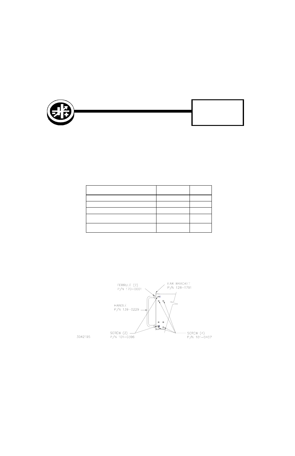
2.2 PROCEDURE (Refer to Figure 1.)
1. Remove any MST modules from the CA 400 rack adapter.
2. Attach handle to one ear bracket using two (2) screws (P/N 101-0396) and ferrule (P/N 170-0001).
3. Position mounting ear (with handle assembled) inside the rack adapter cover at one side, aligning the four (4) threaded
holes of the tab with the corresponding countersunk holes on the cover side panel; attach using four (4) flat head screws
(Kepco P/N 101-0407) provided.
4. Repeat above procedure for the other mounting ear.
FIGURE 1. MOUNTING EAR INSTALLATION, RIGHT SIDE (TYPICAL)
TABLE 1. MATERIAL SUPPLIED
ITEM
KEPCO
PART NUMBER
QUANTITY
• Ear Bracket
128-1791
2
• Handle
139-0229
2
• Ferrule
170-0001
4
• Screw (10-32 X 0.005, ST., FLPO)
Attaches handle to ear brackets
101-0396
4
• Screw (6-32 X 0.187, ST., FLPO)
Attaches ear brackets to CA 400 rack adapter
101-0407
8