Table 1. kes 48 volt specifications (continued) – KEPCO KES 48V User Manual
Page 4
4
228-1600 REV 3
010510
KEPCO, INC. 131-38 SANFORD AVENUE FLUSHING, NY. 11355 U.S.A. TEL (718) 461-7000 FAX (718) 767-1102
www.kepcochargers.com email: [email protected]
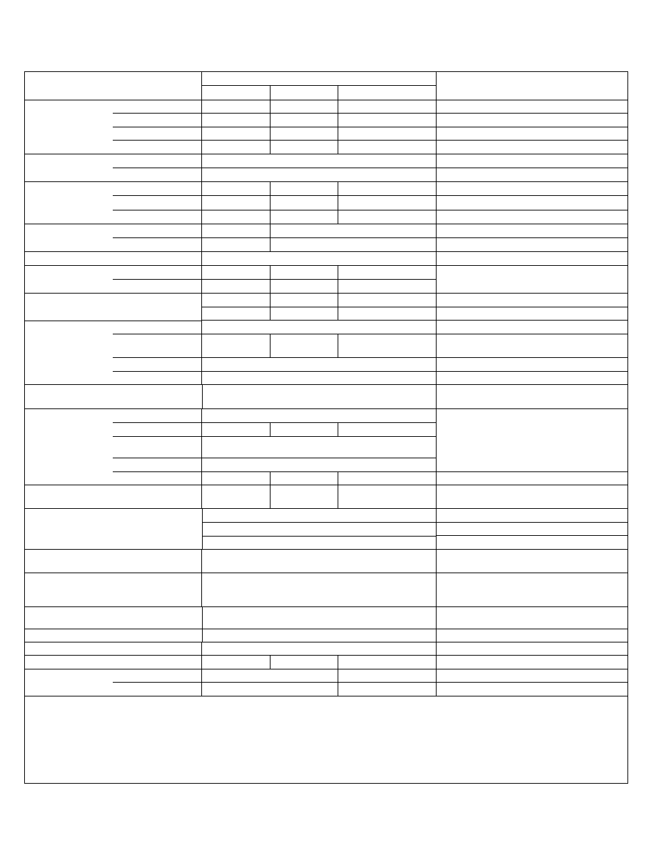
Input Current
100V a-c to 120V a-c
4.4A a-c max.
8.4A a-c max.
22A a-c max.
200V a-c to 240V a-c
2.2A a-c max.
4.2A a-c max.
11A a-c max.
100V a-c to 120V a-c
20A p-p max.
30A p-p max.
20A p-p max.
Surge, cold start, interval > 30 sec
200V a-c to 240V a-c
40A p-p max.
60A p-p max.
40A p-p max.
Surge, cold start, interval > 30 sec
Output Voltage
(Floating)
Factory Setting
52.0Vd-c
0.2% tolerance
Adjustable Range
37.6 - 52.5V d-c
Minimum
Output Current Limit
Factory Setting
5A d-c
10A d-c
25A d-c
4% tolerance
Adjustable Range
1 - 5A d-c
2 - 10A d-c
5 - 25A d-c
Short Circuit
(2)
4.5A d-c
9A d-c
22.5A d-c
For factory-set current limit, 4% accuracy
Output Voltage Rip-
ple and Noise
(4)
Ripple
200mVp-p
300mVp-p
Noise
300mVp-p
400mVp-p
Power Factor
0.99 typical
100V a-c input, rated output
Efficiency
AC input 100V
81%
84%
84%
Rated output
AC input 200V
85%
87%
88%
Leakage Current:
0.34mA a-c typ.
0.55mA a-c typ.
0.65mA a-c typ.
Per IEC 950 and UL 1950 @ 120V a-c, 60Hz
0.46mA a-c typ.
0.75mA a-c typ.
1.25mA a-c typ.
Per IEC 950 and UL 1950 @ 240V a-c, 60Hz
Stabilization
Source Effect
0.2% max.
85 to 132V a-c and 170 to 265V a-c
Load effect
0.4% max.
0.6% max.
0.6% max.
Measured at front panel test points
(5)
, 0-100%
load
Temperature effect
1% max.
–10° to 65°C
Time effect
0.5% max.
8 hours at 25°C
Output Voltage
Temperature Compensation
3mV/(°F)(cell), 5.4mV/(°C)(cell)
0.5% accuracy @ 2.23V cell voltage
(6)
Use optional temperature compensation probe,
0°C to +35°C for Lead-Acid battery.
Output Protection
Overvoltage
(3)
60V d-c
Shutdown upon fault condition.
Overcurrent
(3)
11A d-c
19A d-c
45A d-c
Internal
Overtemperature
(3)
Detected
Fan Failure
(3)
Detected
Battery Reversed
7.25
A d-c
(7)
14.5
A d-c
(7)
36.3
A d-c
(7)
Output limited to a negative Schottky diode drop.
Input Protection
Fuses (2) 10A,
250V
Fuses (2) 25A, 250V
10A: Kepco P/N 141-0057 (Bussman P/N MDA-10)
25A: Kepco P/N 141-0127 (Bussman P/N MDA-25)
Front Panel Display
Analog meter for output (charging) current
0 to maximum current limit, 5% accuracy
“Charger ON” LED
Green indicates charger is on
“Temp Probe Not Connected” LED
Yellow indicates that the probe is not connected
Alarm Output
One form “C“ Relay contact
Terminals: ARMATURE, OPEN, CLOSED.
(8)
Contact Ratings: 120V a-c/0.5A a-c,
24V d-c/1A d-c, 0.1 Ohm (max. ON resistance)
Remote On-Off Input
Isolated ON-OFF control terminals ±RC
ON: Requires short or low voltage
OFF: Requires open or high voltage
ON: 0.4V max., 1.6mA source current
OFF: 2.4V to 24V d-c, 1 mA sink current
Operation Temperature
-10°C to +65°C
Output performance derated above 50°C and
below 0°C
Storage Temperature
-30°C to 75°C
Cooling
Forced air flow - one fan (exhaust to the left side)
Weight
9.0 lbs (4.1 Kg)
12.0 lbs (5.4 Kg)
approx. 22.0 lbs (10 Kg)
Dimensions
(H x W x D)
inches
7.25. x 11.14 x 9
9.25 x 15.16 x 9
millimeters
(184.2 x 283 x 228.6
(235 x 384.6 x 228.6)
(2)
10% of current limit setting value foldback.
(3)
Specification applies to internal power module and results in unit shutdown. To recover, disconnect a-c input, wait about 40 seconds, then reconnect a-
c input.; to recover immediately, toggle the RC control signal OFF, then ON (see Remote On-Off Input, above).
(4)
Ripple & noise = 1.5 x indicated values for Ta = -10°C to 0°C. Values shown are satisfied for 0 to 100% load, 0 to 65°C, measuring bandwidth
≤
100MHz.
(5)
Minimum input impedance of 1 Megohm required for voltage measurement instrument.
(6)
To calculate temperature compensation for cell voltage other than 2.23V, see Section III - Using Temperature Compensation for Lead-acid Battery.
(7)
Output disconnected for output current > 1.45 x rated current limit
(8)
Alarm activates upon detection of missing a-c input, charger not operational, or output current falls below 1% of charger maximum current limit.
TABLE 1. KES 48 VOLT SPECIFICATIONS (CONTINUED)
SPECIFICATION
RATING
DESCRIPTION/CONDITION
KES 48-5
KES 48-10
KES 48-25