Other features, Figure 3. hsp series rear panel connections, Figure 4. component locations – KEPCO HSP Series Quick Start Guide User Manual
Page 4
4
228-1706
091410
KEPCO, INC. 131-38 SANFORD AVENUE FLUSHING, NY. 11355 U.S.A. TEL (718) 461-7000 FAX (718) 767-1102
http://www.kepcopower.com email: [email protected]
recovery to voltage regulation mode is automatic upon
reduction of output current below the current limit point.
Current Limit can also be set to Undervoltage Lockout: if
current mode is maintained for more than 15 seconds, the
output is turned off, and source power must be recycled to
restart the unit. Refer to Operator manual for details.
OTHER FEATURES The following features of the HSP
power supplies are covered in detail in the Operator man-
ual:
• Parallel Operation, including load sharing require-
ments.
• Remote Inhibit, Remote Reset
• Remote Voltage and Current Limit adjustment
• Protection Circuits
• Status Flags and Indicators
• Load Monitor (Current)
• Current “Walk-In” for battery charging applications
• Load monitor
• Auxiliary supply
• Keying
• I/O Connector pin functions
• Options
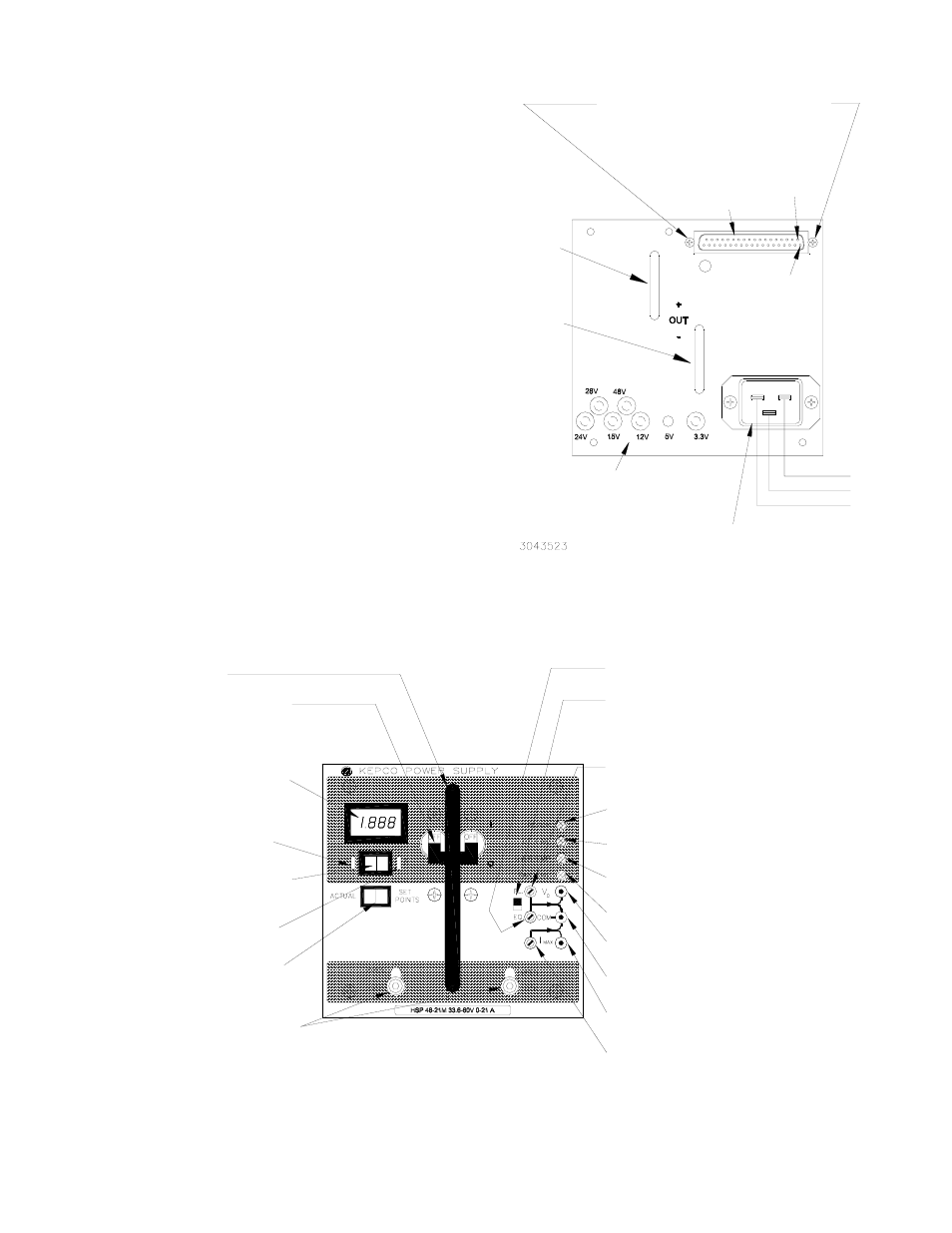
FIGURE 3. HSP SERIES REAR PANEL CONNECTIONS
FIGURE 4. COMPONENT LOCATIONS
Output
Bus Bar
(+)
For Standalone operation, replace
connector mounting screws using
instructions and components supplied
in Standalone accessory KIT 219-0240
or KIT 219-0249.
Output
Bus Bar
(-)
Keyways and Plugs for module
keying (for use with Kepco
plug-in Rack Adapters)
Pin 1
Pin 20
I/O
Connector
Power Inlet
Connector
Line (Hot)
Ground
Neutral
EQ Adjust pot (B suffix only) Used to adjust
Equalize voltage while monitoring Vo and COM.
I
MAX
Adjust pot Used to adjust current limit from
front panel.
COM jack Provides return for Vo and I
MAX
setpoint monitor jacks.
I
MAX
Setpoint monitor jack Used with COM jack to
monitor current limit setpoint.
Vo Setpoint monitor jack Used with COM jack to
monitor voltage setpoint.
OVERTEMP indicator Lights amber to indicate
overtemperature detected.
POWER Indicator Lights green when unit
is operating. Off when fault detected.
ACTUAL/SETPOINTS momentary switch
(M Suffix only) Meter normally shows actual
output voltage or current. Meter shows
setpoints while switch is pressed.
Power ON/OFF circuit breaker Applies
power to the unit. CAUTION: Power must
be OFF before unit is removed from the
rack adapter.
Voltage/Current Meter (M Suffix only)
Monitors output voltage or current per
Meter Mode switch. Remote sensing required
for voltmeter to display voltage at the load.
DC FAIL Indicator Normally off. Lights red to
indicate failure.
FAN FAIL indicator Lights red to indicate fan
failure.
Insertion/Extraction Handle
Vo Adjust pot Used to adjust output voltage
setpoint. Used to adjust Float voltage on
B suffix models.
FL/EQ Select switch (B suffix only) Allows
either Float or Equalize voltage to be monitored
across Vo and COM jacks. CAUTION: Adjust
only the pot selected by FL/EQ switch.
Retaining Latches (2) Prevents inadvertent
removal of unit from rack adapter.
3043522
Meter Mode switch (M Suffix only)
Set to V to show output voltage on meter,
set to A to show output current.
V (Voltage) indicator (M Suffix only)
Lights green when meter shows Volts.
A (Amperes) indicator (M Suffix only)
Lights amber when meter shows Amperes.