Ii — features, Front panel access, Built-in or-ing diodes – KEPCO HSF-1UR 100W Series Operator Manual User Manual
Page 2: Forced current share circuit, Remote on-off, Current monitor, Alarm circuit, Keying, Figure 2. rear connector pin assignments
2
228-1568 REV 8
083013
KEPCO, INC. 131-38 SANFORD AVENUE FLUSHING, NY. 11355 U.S.A. TEL (718) 461-7000 FAX (718) 767-1102
http://www.kepcopower.com email: [email protected]
FIGURE 1. HSF-1UR 100 WATT POWER SUPPLIES (4) INSTALLED IN RA 19-1U RACK ADAPTER
II — FEATURES
FRONT PANEL ACCESS. The front panel provides a
power ON/OFF switch controlling input power and a “VDC
ON” light which indicates when the unit is operating.
NOTE: The ON/OFF switch must be set to OFF before
removing unit from rack adapter. The front panel “MAS-
TER ON” LED lights when 1) the unit operates indepen-
dently, or 2) the unit is used in parallel redundant
configurations while a) the output is less than 10% of
nominal or b) the output is within 10% to 100% of nominal
and the unit is functioning as a master. In parallel redun-
dant configurations, the module with the highest voltage
functions as the master. The other units are slaves, and
track the output voltage of the master. Refer to Current
Share Bus (CSB) on page 3 for details. (For the 3.3V
model, the “MASTER ON” LED has no function and is
always off.) The front panel Vadj trimmer provides adjust-
ment of the output voltage within the limits specified in
Table 1; test points connected to the +S and –S lines are
available at the front panel for measuring the output.
BUILT-IN OR-ING DIODES. OR-ing diodes allow
configuration of all models for hot-swap and parallel-
redundant N+1 operation where current distribution is not
equal and the idle unit takes over in the event of failure.
FORCED CURRENT SHARE CIRCUIT. (Not avail-
able on 3.3V model). When units are configured for N+1
parallel redundant operation, it is desirable (but not
required) for current to be divided equally among the paral-
leled supplies. When the CSB (forced Current Share Bus)
lines of paralleled HSF-1UR units are connected together,
the load current is forced to divide equally between all par-
alleled units; units operate at less than maximum, reducing
stress and increasing reliability of the system. If one unit
fails, the remaining units will continue to supply the load,
and the load current will be divided equally among the
remaining operating units. The failed unit is automatically
isolated from the circuit by a built-in isolation diode. Refer
to Current Share Bus (CSB) on page 3 for details.
REMOTE ON-OFF. Remote on-off (X and Y models
only) is via ±RC assigned to pins of the RA 19-1U I/O con-
nector: off = no voltage, short circuit, or 0 to 0.8V, on = 4.5
to 12.5V (or 12.5 to 24.5V via 1.5K Ohms). To reverse on-
off polarity contact Kepco. There is no isolation between
±RC, d-c output and alarm circuit. Refer to the RA 19-1U
Manual for details.
CURRENT MONITOR. Current monitor (C and Y
models only) is via ±IMON assigned to pins of the RA 19-
(X)B I/O connector. Monitored Output Current (Amps) =
Voltage drop across R
EQ
(mVolts) / R
EQ
(mOhms) where
R
EQ
is the sum of R
S
(see Table 1) + trace resistance to
point where current monitor is connected, approximately
4mOhms. The voltage drop across R
EQ
is measured
across ± IMON pins (requires millivoltmeter, range 0 to
250mV). Accuracy is ±10%; contact Kepco if greater
accuracy is required. There is no isolation between
±IMON, alarm circuit and d-c output. Refer to the applica-
ble RA 19-1U Manual for details.
ALARM CIRCUIT. The HSF-1UR includes an isolated
internal relay offering normally closed and normally open
contacts referenced to an isolated common. These con-
tacts may be used to configure “close on failure” or “open
on failure” alarm circuits. (Refer to the RA 19-1U Manual
for alarm configurations for multiple HSF-1UR power sup-
plies.)
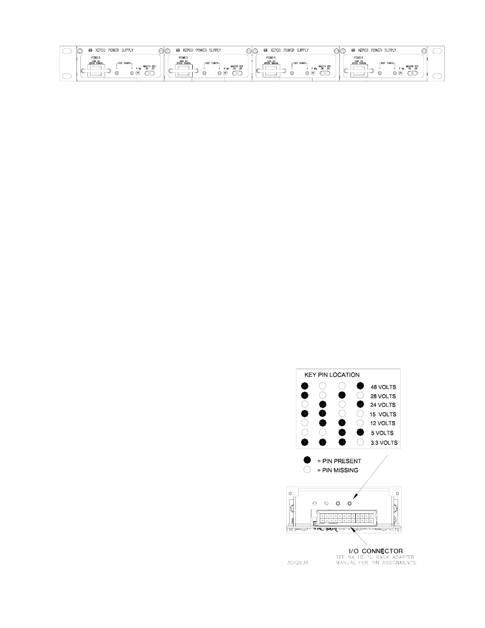
KEYING. Keying of the HSF-1UR is established at the
factory (see Figure 2). The output voltage determines
which key pins are installed. When the proper holes in the
rack adapter are blocked by keying screws installed by the
user, only a power supply of the correct voltage can be
inserted in the rack adapter slot. (Refer to the RA 19-1U
Manual for rack adapter keying instructions.)
FIGURE 2. REAR CONNECTOR PIN ASSIGNMENTS
PS2
PS1
3042496
PS4
PS3