KEPCO HSF 1500W Series (all models) Quick Start Guides User Manual
Kepco, Single output 3u hot swap plug-in power supplies, I — introduction
©2013, KEPCO, INC
1
Data subject to change without notice
228-1704 REV 1
KEPCO, INC. " 131-38 SANFORD AVENUE " FLUSHING, NY. 11355 U.S.A. " TEL (718) 461-7000 " FAX (718) 767-1102
http://www.kepcopower.com " email: [email protected]
Q U I C K S T A R T G U I D E
KEPCO
An ISO 9001 Company.
HSF
1200W/1500W
SINGLE OUTPUT 3U
HOT SWAP PLUG-IN POWER SUPPLIES
I — INTRODUCTION
SCOPE OF MANUAL. This Quick Start Guide covers
the installation and operation of the Kepco HSF 1200W/
1500W Series of Hot Swap Plug-in Power Supplies. Full
specifications are listed in the HSF 1200W/1500W Opera-
tor Manual that can be downloaded from the Kepco web
site at:
www.kepcopower.com/support/opmanls.htm#hsf
These power supplies are designed to be installed in
Kepco’s RA 19-4C Rack Adapter. The RA 19-4C Operator
Manual can be downloaded from the Kepco web site at:
www.kepcopower.com/support/opmanls.htm#ra19-4c
FACTORY DEFAULTS. This guide covers only units as
shipped from the factory with the two internal DIP switches
set to default configuration (see Figure 1). For other config-
urations, refer to applicable Operator Manual.
DESCRIPTION. The Kepco HSF 1200W/1500W Series
are hot swappable, high frequency switching, plug-in power
supplies. Models may be selected for outputs of 24V, 36V
or 48V. They employ power factor correction and are
designed to operate in a fault tolerant power system with a
nominal a-c input of 100V a-c to 240V a-c (input voltage
range 85 to 265 Va-c), 50-60 Hz (input frequency range 47-
440Hz). A built-in current balancing circuit and OR-ing
diodes allow configuration for hot-swap and parallel-redun-
dant N+1 operation. All input/output connections are
through a 24-pin connector that plugs in to the rack
adapter. All external connections are made through the
rack adapter’s I/O connector.
OPTIONS. M models include a digital meter which dis-
plays either voltage or current as determined by a front
panel switch. The front panel V or A indicator lights to show
whether voltage (V) or current (A) is displayed. Metered
and non-metered models are completely interchangeable.
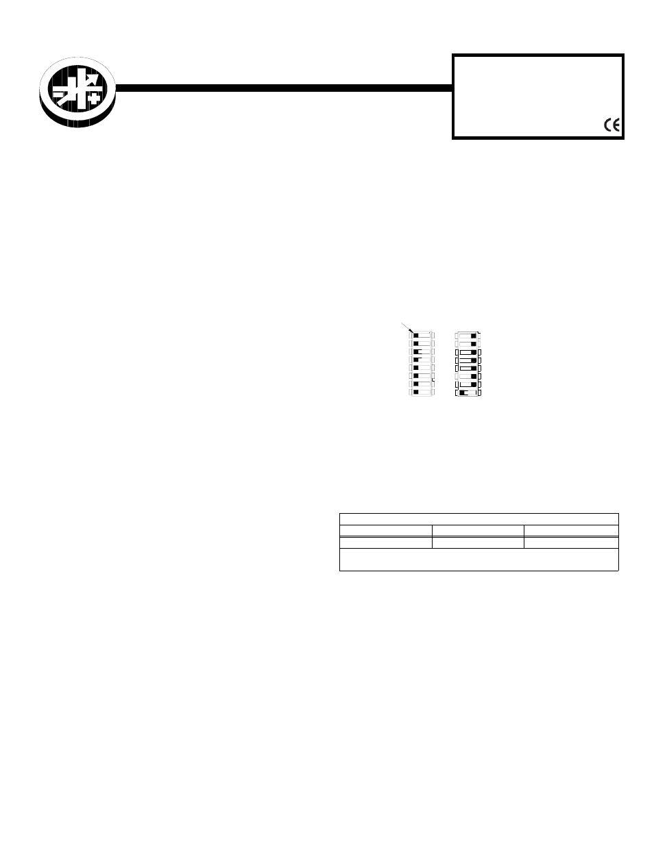
FIGURE 1. DIP SWITCH FACTORY DEFAULTS
C Models include a current sense resistor which allows
external current monitoring within 3% (contact Kepco if
greater accuracy is required). RoHS-compliant models
indicated by HSF* (e.g., HSF 24*50M).
II — INSTALLATION
PRIOR TO MOUNTING. Two internal DIP switches are
preconfigured for the factory defaults (see Figure 1). To
change the factory defaults, refer to the operator manual
and configure the DIP switches prior to installation.
KEYING. The units are keyed by voltage at the factory.
Refer to the RA 19-4C Operator Manual to make the rack
adapter slot match the HSF.
MOUNTING THE POWER SUPPLY. Release the two
cap head screw retaining latches (see Figure 2) by loosen-
ing the cap-head screw approximately 1/2 turn CCW (use
5/32" hex key) and slide to the open (up) position. Insert the
power supply in the slot, then retighten the cap-head
screws CW until snug. DO NOT OVERTIGHTEN! To
release, follow the same procedure, except lift the latch to
the top of the slot. Be sure to move the latch completely up
or down to ensure full engagement and disengagement of
the latching mechanism. When the HSF is not installed in
its plug-in rack adapter, it is recommended that the latch be
secured in the open (up) position to prevent damage.
TABLE 1. HSF 1200W/1500W HOT SWAP MODELS
MODELS
24V
36V
48V
HSF 24-50
HSF 36-42
HSF 48-32
NOTE: Options include suffix M, or C: M for meter, C for current monitor.
HSF* indicates RoHS compliance.
3043519
- FRONT PANEL VADJ CONTROL
- RELAY ALARM SELECTED
- VISUAL ALARM DISABLED
- REMOTE ON-OFF DISABLED
Factory default settings
for all options
1
2
3
4
5
6
7
8
8
SW1
SW2
2
5
5
7
8
6
7
8
6
3
4
4
3
5
7
6
4
3
ON
1
2
OFF
1
2
OFF
1
ON
TAB