Removal, Figure 2. component locations, Iii — operation – KEPCO HSF 300W Series (no suffix, suffix M and MZ) Quick Start Guides User Manual
Page 2
2
228-1703 REV 1
022613
KEPCO, INC. " 131-38 SANFORD AVENUE " FLUSHING, NY. 11355 U.S.A. " TEL (718) 461-7000 " FAX (718) 767-1102
http://www.kepcopower.com " email: [email protected]
REMOVAL. To remove a power supply, first use the
POWER switch to turn off the unit. Release the two cap
head screw retaining latches (see Figure 2) by loosening
the cap-head screw approximately 1/2 turn CCW (use 5/
32" hex key) and slide to the open (up) position. Then
extract the unit from the RA 19-4C Rack Adapter. CAU-
TION: The ON/OFF switch must be set to OFF before
removing the unit from the rack adapter. Leave the
latches in the open position when not installed.
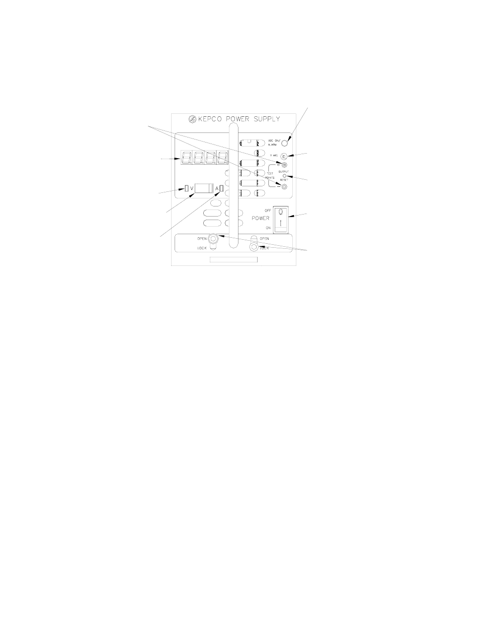
FIGURE 2. COMPONENT LOCATIONS
III — OPERATION
Turn the unit on using the front panel POWER switch (see
Figure 2). CAUTION: DO NOT repeatedly toggle the
POWER on/off switch as this may cause unit to fault.
When output voltage is within range specified in applica-
ble Operator Manual, the VDC ON LED is on (green). The
VDC ON indicator can be configured to light red to indi-
cate a loss of output voltage (see applicable Operator
manual). NOTE: Except for MZ models, a minimum
output voltage is required to keep the internal relay
and optional meter functioning (see applicable Opera-
tor manual).
While monitoring output voltage at the front panel test
points, the V ADJ Output Voltage Adjust trimmer allows
adjustment of the output voltage. The unit can also be
configured to control output voltage using a remote resis-
tance or voltage (see applicable Operator manual).
The OUTPUT RESET switch can be used to recycle
power in the event of an alarm condition. This switch does
not function if the remote on/off feature has been enabled
(see applicable Operator manual).
The following features of the HSF 300W power supplies
are covered in the applicable Operator manual:
• Parallel Operation, including current balancing
requirements. Parallel operation with current balanc-
ing (forced current sharing) is recommended to
increase reliability and results in minimal output volt-
age bus variation upon shutdown of one unit is a
fault-tolerant configuration.
NOTE: To avoid false alarm triggers or unit shutdown
when operating units in parallel, 300W models
(all options) require voltage set restrictions as
specified in the applicable Operator Manual.
• Remote On/Off and Voltage adjustment
• Protection Circuits
• Alarms
• Keying
• Local/Remote Sensing (Remote error sensing is rec-
ommended for correct setting of output voltage.)
• Options
Voltage/Current Meter (M, MZ Suffix only)
Monitors output voltage or current
per
Meter Mode switch.
R
emote sensing
required
for
voltmeter to display voltage at the load.
VDC ON/ALARM Indicator Lights green when
unit is operating.
Can be configured
by DIP switch
to light red to indicate loss of output voltage in
parallel configurations. All models allow
select
ion
of
whether
indicator is powered by output or
will
function down to 0V
.
V. ADJ Output Voltage Adjustment Trimmer:
Adjusts output voltage. Not functional if
remote voltage control is enabled
.
TEST POINT (±) Connect to external
voltmeter to monitor d-c output voltage.
OUTPUT RESET switch Used to recycle
power in the event of an alarm condition.
Not functional when remote on/off control
is enabled.
POWER ON/OFF switch Applies power
to the unit. CAUTION: Power must be
OFF before unit is removed from the
rack adapter.
Retaining Latches (2) Prevents inadvertent
removal of unit from rack adapter.
3043507
Meter Mode slide switch (M, MZ Suffix only)
Set to V to show output voltage on meter,
set to A to show output current.
V (Voltage) indicator (M, MZ Suffix only)
Lights green when meter shows Volts.
A (Amperes) indicator (M, MZ Suffix only)
Lights
amber
when meter shows
Amperes
.