KEPCO DIN KIT RKW-1500 (L) User Manual
Kepco
©2003, KEPCO, INC
1
Data subject to change without notice
228-1476
I N S T R U C T I O N M A N U A L
KIT
KEPCO
KEPCO, INC. " 131-38 SANFORD AVENUE " FLUSHING, NY. 11352 U.S.A. " TEL (718) 461-7000 " FAX (718) 767-1102
http://www.kepcopower.com " email: [email protected]
An ISO 9001 Company.
DIN RKW1500-L
DIN-RAIL MOUNTING KIT
FOR SERIES RKW 1500W
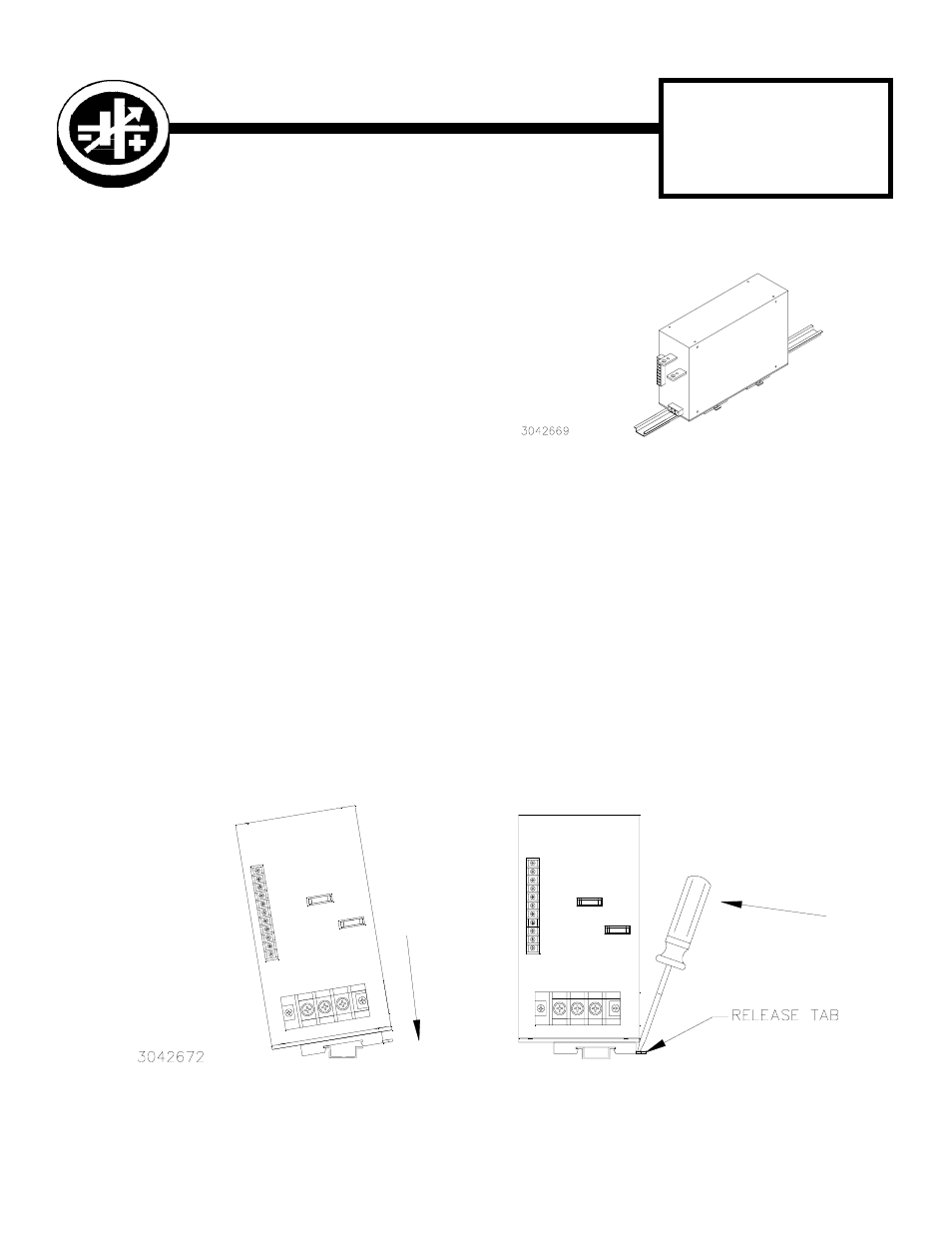
FIGURE 1. L SUFFIX ORIENTATION
REMOVING POWER SUPPLY FROM DIN RAIL. While grasping the power supply with one hand, use a screwdriver to
apply leverage towards the left as shown in Figure 3B to disengage both clips from the rail.
FIGURE 2. INSTALLATION AND REMOVAL OF POWER SUPPLY FROM DIN RAIL
A -
INSTALLATION
B -
REMOVAL
DESCRIPTION. Kepco Kit, Model DIN RKW 1500-L con-
tains a preassembled mounting plate and associated hard-
ware used to install RKW 1500 Watt Series power supplies
on a DIN rail. The “L” suffix is for mounting perpendicular
to the long dimension (length) as shown in Figure 1. Out-
line dimensions are shown in Figure 4.
INSTALLATION.
1. INSTALLING KIT. Attach the preassembled mounting
plate to the power supply using the hardware supplied (see
Figure 3).
2. INSTALLING POWER SUPPLY ON DIN RAIL. To mount the power supply on the rail insert one end of both clips
under one edge of the rail, then snap the other end of the clips into place (see Figure 2A).
NOTE: For applications where the installed power supply may be subject to unusual levels of shock or vibration, or
where the power supply is oriented such that it may slide down the rail due to gravity, the use of two DIN rail
end stops (Kepco P/N 108-0367) is recommended. After installing the power supply on the rail, the end stops
are installed by clearing the DIN rail of other components and sliding the end stops over the rail. When the end
stops are secure against the power supply, tighten the two integral screws of each end stop.
3. WIRE POWER SUPPLY. Refer to RKW 1500W manual.