KEPCO DIN KIT RKW-150 (S) User Manual
Kepco
©2003, KEPCO, INC
1
Data subject to change without notice
228-1455
I N S T R U C T I O N M A N U A L
KIT
KEPCO
KEPCO, INC. " 131-38 SANFORD AVENUE " FLUSHING, NY. 11352 U.S.A. " TEL (718) 461-7000 " FAX (718) 767-1102
http://www.kepcopower.com " email: [email protected]
An ISO 9001 Company.
-150S
DIN RKW
DIN-RAIL MOUNTING KIT
FOR SERIES RKW 150W
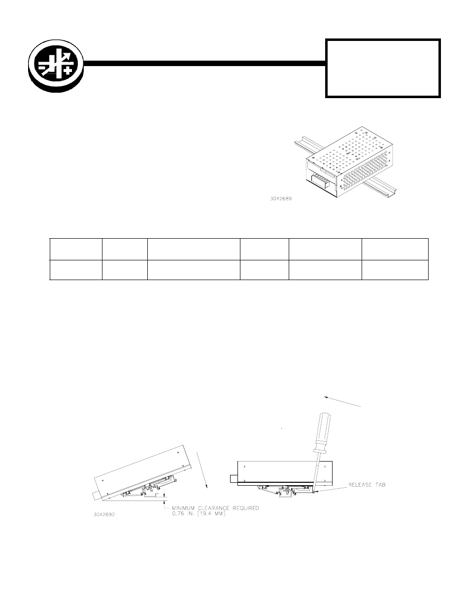
FIGURE 1. S SUFFIX ORIENTATION
INSTALL COVER. Attach the cover to the power supply per instruction manual supplied with the cover.
INSTALLING KIT. Attach the preassembled mounting clips to the power supply using the hardware supplied (see Fig-
ure 3). The clips may be mounted with the release lever on either side to facilitate removal.
INSTALLING POWER SUPPLY ON DIN RAIL. To mount the power supply on the rail insert one end of both clamps
under one edge of the rail, then snap the other end of the two clips into place (see Figure 2A).
REMOVING POWER SUPPLY FROM DIN RAIL. While grasping the power supply with one hand, use a screwdriver to
apply leverage towards the left as shown in Figure 2B to disengage each clip from the rail. Where mounting clips are
close together, it may be necessary to apply leverage with two screwdrivers simultaneously.
FIGURE 2. INSTALLATION AND REMOVAL OF POWER SUPPLY FROM DIN RAIL
TABLE 1. COMPONENTS SUPPLIED
KIT
MODEL NO.
COVER
PART NO.
MOUNTING PLATE (QTY 2)
PART NO.F
CLIP (QTY 2)
PART NO.
SCREW (QTY 4)
PART NO.
WASHER (QTY 4)
PART NO.
DIN RKW-150S
CA 36
128-2125
108-0362
501-0075
(M4 X 8 BN FHPH)
103-0017
(NO. 8, INT. TOOTH)
A —
INSTALLATION
B —
REMOVAL
DESCRIPTION. Kepco KITs, Models DIN RKW-150S,
contains two preassembled mounting clips and associ-
ated hardware used to install RKW 150 Watt Series
power supplies on a DIN rail. The “S” suffix is for mount-
ing along the short dimension (width) as shown in Figure