KEPCO DIN KIT ERX-120 (S) User Manual
Kepco
©1998, KEPCO, INC
1
Data subject to change without notice
228-1324
I N S T R U C T I O N M A N U A L
KIT
KEPCO
KEPCO, INC. " 131-38 SANFORD AVENUE " FLUSHING, NY. 11352 U.S.A. " TEL (718) 461-7000 " FAX (718) 767-1102
http://www.kepcopower.com " email: [email protected]
An ISO 9001 Company.
DIN ERX
-120S
DIN-RAIL MOUNTING KIT
FOR SERIES ERX 120W
.
FIGURE 1. S SUFFIX ORIENTATION
INSTALLATION
1. INSTALL COVER. Attach the cover to the power supply per Instruction Manual supplied with the cover.
2. INSTALL CLIPS. Attach left and right clips to power supply using hardware supplied (see Figure 3).
3. INSTALL CABLE KIT. Attach wires to the power supply per Instruction Sheet supplied with cable kit.
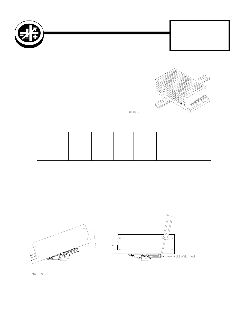
FIGURE 2. INSTALLATION AND REMOVAL OF POWER SUPPLY FROM DIN RAIL
TABLE 1. COMPONENTS SUPPLIED
KIT
MODEL NO.
COVER
PART NO.
CABLE KIT
PART NO.
CLIP
(QTY 2)
PART NO.
BRACKET
(QTY 2)
PART NO.
SCREW
(QTY 4)
PART NO.
WASHER
(QTY4)
PART NO.
DIN ERX-120S
CA 17
219-0146
108-0362
128-1965
101-0383
(8-32 X 0.187
PHPH)
103-0032
(NO. 8, SPLIT,
LOCK)
NOTE: Clip and Bracket are supplied preassembled into left and right mounting clip assemblies. To replace a mounting
clip assembly, order both the clip and bracket and assemble per Figure 3 detail.
DESCRIPTION. Kepco KIT, Model DIN ERX-
120S contains a cover, cable kit, left and right
mounting clips, and associated hardware (see
Table 1) used to install ERX Series 120W power
supplies on a DIN rail. The “S” suffix is for
mounting along the short dimension (lwidth) as
shown in Figure 1. Outline dimensions are
shown in Figure 4.
B
REMOVAL
INSTALLATION
A