KEPCO DIN KIT ECM (P) User Manual
Kepco, Din ecm -p din-rail mounting kit for series ecm
©1998, KEPCO, INC
1
Data subject to change without notice
228-1408
I N S T R U C T I O N M A N U A L
KIT
KEPCO
KEPCO, INC. " 131-38 SANFORD AVENUE " FLUSHING, NY. 11352 U.S.A. " TEL (718) 461-7000 " FAX (718) 767-1102
http://www.kepcopower.com " email: [email protected]
An ISO 9001 Company.
DIN ECM
-P
DIN-RAIL MOUNTING KIT
FOR SERIES ECM
FIGURE 1. P SUFFIX ORIENTATION
INSTALLATION
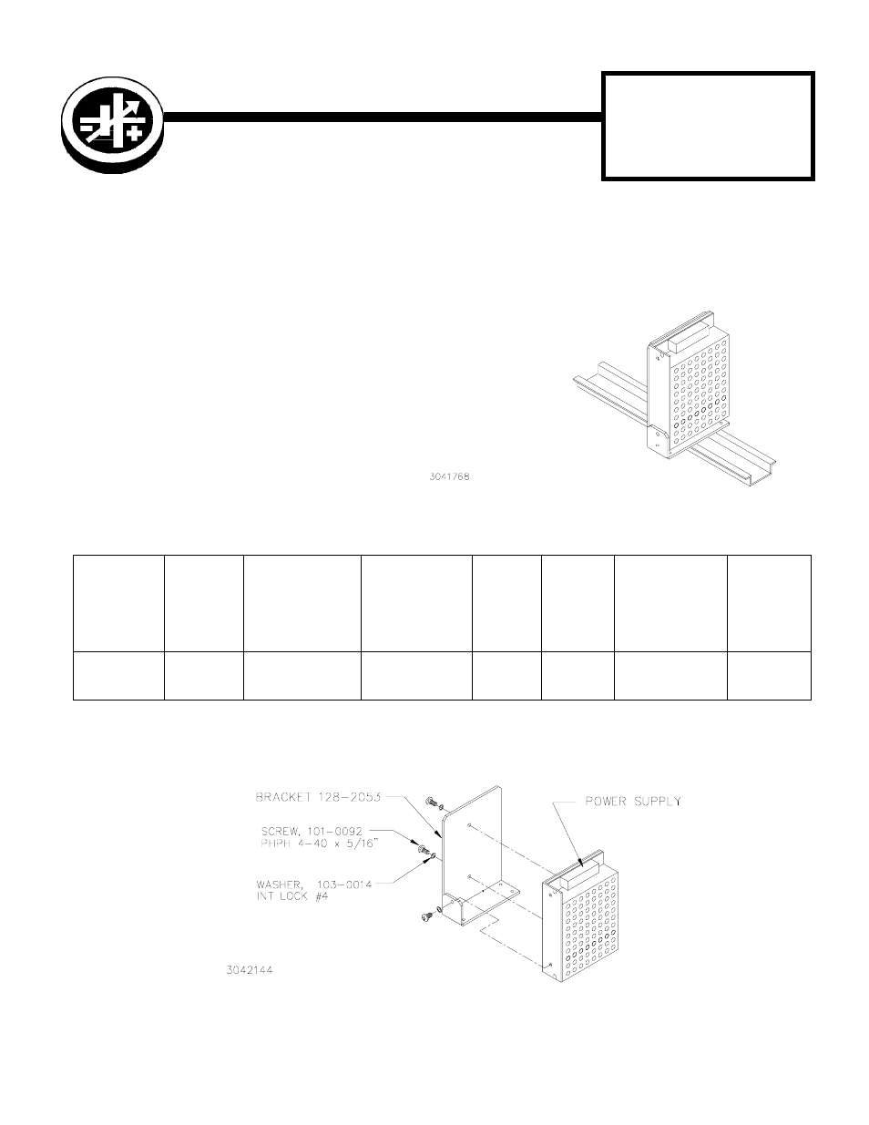
1. INSTALL MOUNTING BRACKET. Attach the mounting bracket to the power supply using the hardware sup-
plied (see Figure 2).
FIGURE 2. INSTALLING MOUNTING BRACKET ON POWER SUPPLY
TABLE 1. COMPONENTS SUPPLIED
KIT
MODEL NO.
MOUNTING
BRACKET
PART NO.
SCREW
(QTY 3)
(Power Supply To
Mounting Bracket)
PART NO.
WASHER (QTY 3)
(Power Supply To
Mounting Bracket)
PART NO.
CLIP
(QTY 2)
PART
NO.
CLIP
PLATE
(QTY 2)
PART NO.
SCREW
Thread-form
(QTY 4)
(Clip To Mounting
Bracket)
PART NO.
WASHER
(QTY 4)
(Clip To
Mounting
Bracket)
PART NO.
DIN ECM-P
128-2053
101-0092
(4-40 X 5/16 BHPH)
103-0014
(NO. 4, INT.
TOOTH)
108-0366
128-1971
101-0443
(4-40 X 1/4 BHPH)
103-0014
(NO. 4, INT.
TOOTH)
DESCRIPTION. Kepco KIT, Model
DIN ECM-P contains a mounting
bracket with left and right preassem-
bled mounting clips and associated
hardware used to install ECM Series
power supplies on a DIN rail. The “P”
suffix is for mounting the power sup-
ply perpendicular to the DIN rail as
shown in Figure . Outline Dimensions
are shown in Figure 5.