KEPCO CA 34 User Manual
Ca 34, Kepco, Cover enclosures and hardware systems
©2005, KEPCO, INC
1
Data subject to change without notice
228-1451 REV 1
I N S T R U C T I O N M A N U A L
KEPCO
KEPCO, INC. " 131-38 SANFORD AVENUE " FLUSHING, NY. 11352 U.S.A. " TEL (718) 461-7000 " FAX (718) 767-1102
http://www.kepcopower.com " email: [email protected]
An ISO 9001 Company.
CA 34
COVER
ENCLOSURES AND
HARDWARE SYSTEMS
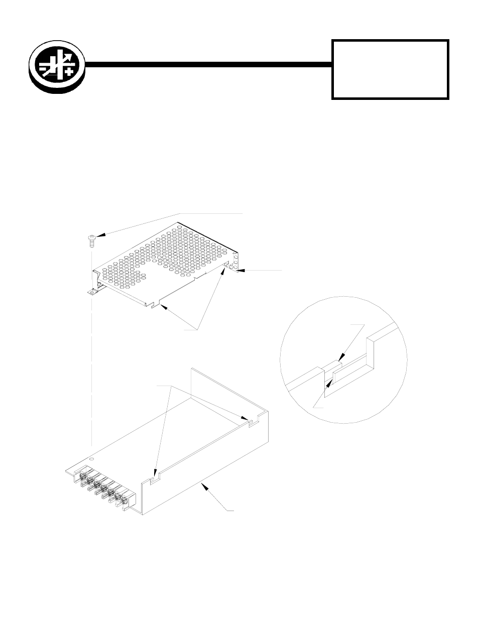
DESCRIPTION. The Kepco Model CA 34 Cover (see Figure 1) is supplied for use with Kepco Series RKW 50 Watt
power supplies. The cover is installed by first removing one screw (M3 X 8) from the RKW power supply (see Figure 1).
Then slide the cover onto the power supply, matching the tabs as shown in Detail A, and secure with screw previously
removed. This screw must not be overtightened (max. torque 10 in.- lbs (1.1 N x m). See Figure 2 for outline dimen-
sions.
FIGURE 1. CA 34 COVER INSTALLATION
RKW TAB
RKW 50W POWER SUPPLY
CA 34 COVER
REMOVE EXISTING SCREW (M3 x 8) FROM
RKW POWER SUPPLY AND USE TO SECURE
COVER TO POWER SUPPLY.
MAX TORQUE 10 1N.-LBS (1.1N x m)
RKW TAB
3042541
SEE DETAIL A
SEE DETAIL A
COVER TAB
COVER TAB
DETAIL A