Cooling – KEPCO BOP 100W, 200W, 400W (M, D) Quick Start Guide User Manual
Page 4
4
228-1678
071609
KEPCO, INC. " 131-38 SANFORD AVENUE " FLUSHING, NY. 11355 U.S.A. " TEL (718) 461-7000 " FAX (718) 767-1102
http://www.kepcopower.com " email: [email protected]
INPUT A-C CONNECTIONS. Install the line cord (sup-
plied) at the rear panel and connect to 115V a-c, 60Hz
(105V to 125V a-c, 50 to 65Hz) mains. Refer to the full
Operator Manual (see PAR. 1.1). For operation at 104V a-
c, 208V a-c or 230V a-c refer to the full Operator manual
(PAR 1.1).
A-C GROUND. The 3-wire line cord with 3-prong safety
plug (supplied), in combination with a properly grounded
a-c power outlet, automatically grounds the BOP case. If
an adapter for a non-grounded outlet is used, the case
must be grounded separately using a separate GROUND
terminal at either the front or rear panel. The ground wire
must be rated for at least the BOP input current (as noted
on nameplate at rear of unit).
D-C SIGNAL GROUND. Specified ripple and noise fig-
ures for BOP power supplies are valid only with the COM-
MON side of the output load circuit returned to a ground
point. The BOP circuits, including output and program-
ming terminals, have no d-c connection to the chassis.
The COMMON terminal of the BOP can be “floated” up to
500 volts (d-c or peak) off a-c ground. The common mode
current (leakage from output to ground) Is less than 50
µ
A
(rms) or 5 mA (p-p) at 115V a-c power input, 60 Hz. To
avoid common mode current from affecting the BOP out-
put, the system (including the programming device, if
used, load, and BOP) must have a single connection to
ground (earth ground). The d-c ground wire must be rated
for the nominal output current of the BOP (e.g, for BOP
20-10M, use rating of 10A).
Multiple signal grounds in the system may cause “ground-
loop” problems, since noise signals develop across the
impedances between the multiple ground points. The
exact physical location of the “best” single ground point
must be carefully selected for minimum ripple/noise out-
put.
3.5. COOLING. The components in the BOP power
supply rely on forced air cooling. SIDE PANEL OPEN-
INGS AND THE TOP OF THE CASE MUST BE KEPT
CLEAR FROM ALL OBSTRUCTIONS TO ENSURE AIR
CIRCULATION. Periodic cleaning of the interior of the
power supply is recommended. If the BOP is rack-
mounted or installed into confined spaces, care must be
taken that the ambient temperature (the temperature
immediately surrounding the power supply) does not rise
above 55°C (~157°F).
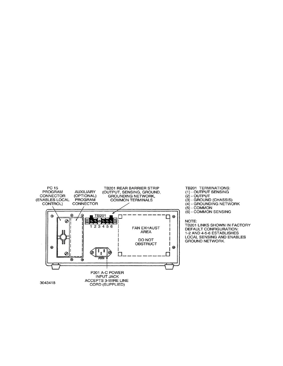
FIGURE 4. BOP REAR PANEL TERMINATIONS