Caution – HT instruments HT401 User Manual
Page 16
HT401
EN - 15
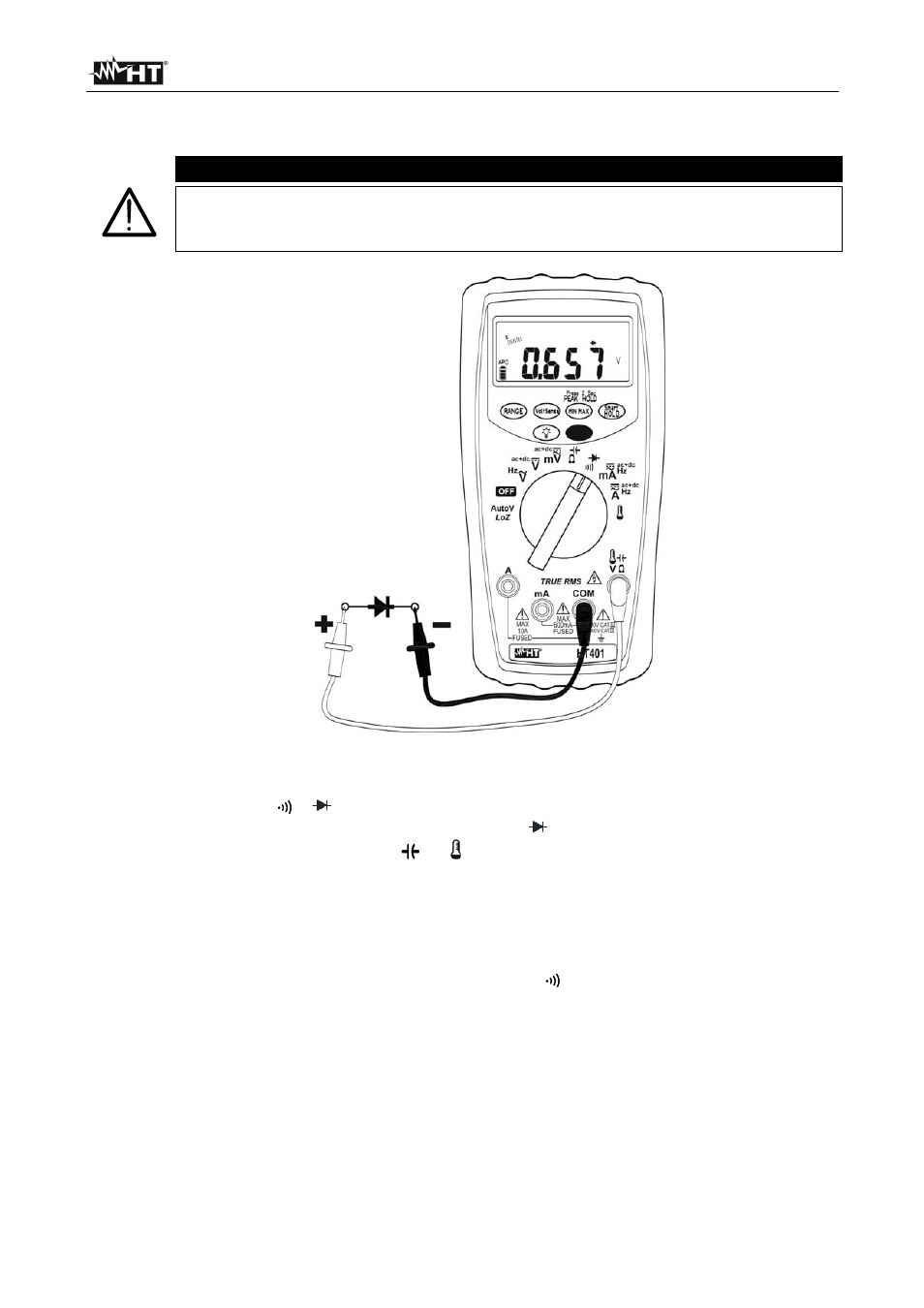
4.4.7. Diode and Continuity test
CAUTION
Before attempting any resistance measurement, cut off power supply from
the circuit to be measured and make sure that all capacitors are discharged,
if present.
Fig. 8: Diode and continuity test
1. Select the position
/
2. Press the MODE key to start testing diodes. The “
” symbol is shown at display
3. Insert the red cable into input lead
V
and the black cable into input lead COM
4. Connect the red lead to the anode and the black lead to the cathode of the diode (see
Fig. 8). The instrument’s display shows the direct polarization voltage. This voltage is
typically 0.4 ~ 0.9V with good junctions.
5. Reverse connections and measure potential drop at the ends of the diode. An “O.L”
result on the display indicates the correct operation of the junction.
6. Press the MODE key to select Continuity test. The “
” symbol is shown at display
7. Insert the red and black cables as described in “Resistance measurement” to carry out
the measurement. The buzzer is ON for resistance values < 30
8. For HOLD function please refer to § 4.2