Figure 18 interconnect wiring – Detcon 1600-N4X-RD User Manual
Page 19
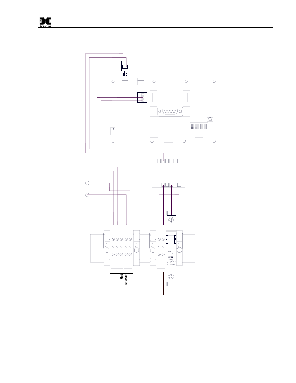
1600/6400-N4X-RD
TB1
3
2
1
Whi
te 18A
WG
Green
16AWG
Black 18AWG
Red 18AWG
Whi
te 22A
W
G
P
u
rple
22A
W
G
Purple 22AWG
White 22AWG
Black 18AWG
N
eut
ral (L2)
VAC (L
1)
Customer Supplied Power
Interface Connections
Legend:
Pre-Wired
Customer Wired
O
I
2A
24VDC Power
Supply
1
2
3
4
5
6
2
-
1
Gnd
L1
N
+
NFS40-7624
P1
J1
J1
+
Red 18AWG
Black 18AWG
8
7
6
Gro
und
A
B
RS-485
5
4
RESET
S2
6400 Controller PCB
Serial Communications
No Comm
VDC IN
RS-485
Input
C
NO
NC
Fault Relay PCB
PCB
S
B
A
+
-
A
B
S
Output
S1
RV1
J4
J3
J3
J7
J1
8 7 6 5 4 3 2 1
1 2
Remote Alarm
Reset PCB
RS-232 I/O
2
1
SW1
Gray 18A
WG
Gray 18A
WG
Remote Alarm
Reset Switch
Figure 18 Interconnect Wiring
1600/6400-N4X-RD- Instruction Manual Rev. 1.0
Page 15 of 16
This manual is related to the following products: