Figure 17 component layout – Detcon 1600-N4X-RD User Manual
Page 18
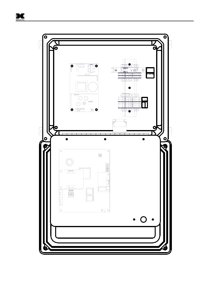
1600/6400-N4X-RD
O
I
2A
L1
P1
F1
N
J1
3
+
5
4
6
2
+
1
J2
VAC (L
1)
Ground
A
B
RS-
4
8
5
RE
SE
T
S2
6400
Con
tr
o
lle
r
PCB
Se
ri
al
Commu
ni
c
a
ti
o
n
s
No Co
mm
V
DC IN
RS
-4
85
Input
C
NO
NC
F
aul
t Rel
a
y P
C
B
PCB
S
B
A
+
-
A
B
S
Out
put
S1
RV
1
J4
J3
J
3
J
7
J1
8
7
6
5 4
3 2 1
1
600/64
00 Remote
D
isp
la
y
PCA
P
o
wer
Su
ppl
y
Input Power
Custom
er
Conne
cti
o
n
s
Figure 17 Component Layout
1600/6400-N4X-RD- Instruction Manual Rev. 1.0
Page 14 of 16
This manual is related to the following products:
See also other documents in the category Detcon Equipment:
- 12B (16 pages)
- FL-10 (7 pages)
- 10C Facilities (18 pages)
- 10C (29 pages)
- 10B (10 pages)
- 1212-N4X (9 pages)
- 812-N4X (9 pages)
- 1212B (5 pages)
- 612B (5 pages)
- 1610-N4X (28 pages)
- 1010-N4X (14 pages)
- 610-N4X (12 pages)
- 1610-N1 (4 pages)
- 810-N1-24VDC (10 pages)
- 410-N1-24VDC (4 pages)
- MCX-32-N1P (55 pages)
- RD-64X-N4X (41 pages)
- 880RA-N4X (36 pages)
- 880RA-N4X (23 pages)
- 880A-N1R (45 pages)
- 880A-N4X (43 pages)
- 880A-N4X (50 pages)
- X40-08-N4X (70 pages)
- 240 (33 pages)
- SW-AV1-N4 (12 pages)
- SW-AV2-DV1 (12 pages)
- A1V1 (9 pages)
- RXT-300 (47 pages)
- RXT-320 (31 pages)
- CXT-N4X (28 pages)
- SW-HMI-32-N4X (24 pages)
- SW-V1-DV2 (11 pages)
- SW-AV1-DV1 (14 pages)
- SW-AV2-DV2 (12 pages)
- SW-AV1-DV2 (12 pages)
- SmartWireless CX (33 pages)
- SmartWireless CXT (49 pages)
- CX-IR (38 pages)
- CX-DM (44 pages)
- CXT-IR (48 pages)
- CXT-DM (56 pages)
- P-1000 (28 pages)
- 1000 (32 pages)
- 1000_CO2 (32 pages)
- 1000_H2S (34 pages)