Remote display sensor configuration form – Detcon RD-4X User Manual
Page 6
Detcon RD-4X Remote Display Monitor PG.6
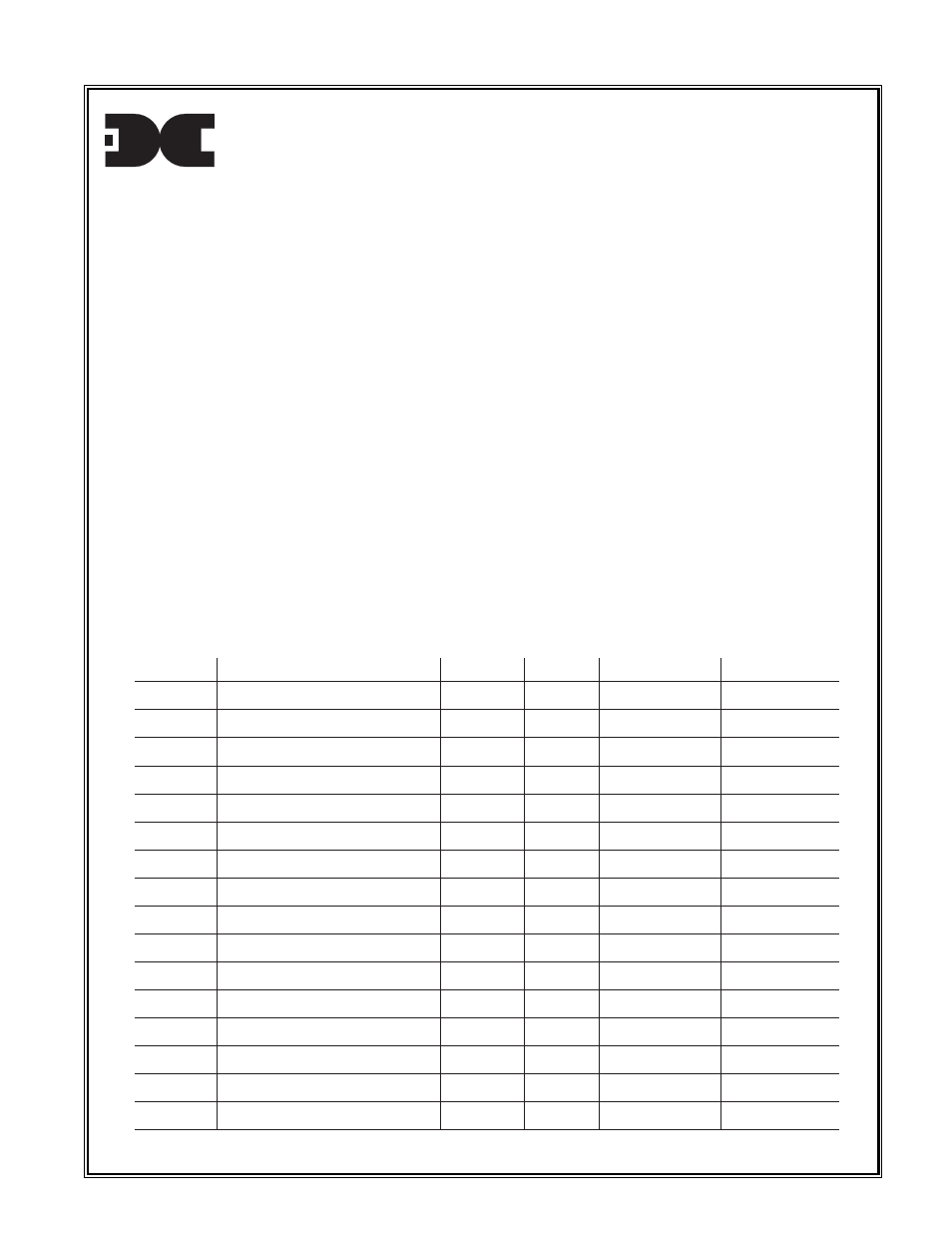
Remote Display Sensor Configuration Form
January 1, 1997 Document # 1737
Channel #
Location
Range
Gas Type Alarm 1 (low)
Alarm 2 (high)
Detcon Model RD-4X and RD-7X are remote display monitors that provide information on up
to 16 remote gas sensor devices. Each channel, numbered 1 through 16, corresponds with the
output of a mating multiplexer PCB assembly (Detcon part #5216) which terminates up to 16
4-20 mA sensor devices and transmits that information to the remote display via a two conductor
RS-485 data line.
In order to properly display the conditions at each sensor location, the remote display’s
microproccessor must be programmed to properly recognize each sensor location’s gas type,
range of detection, and alarm set points. The location of each sensor is also needed so as to
provide a custom adhesive label that should be placed on the face plate next to the display.
To accomplish these two tasks, fill out the information below and return to Detcon, Inc.
Reference the illustration on the following page for typical layout of the remote display
information.
detcon inc.
Examples
Location: Drill Floor, Shale Shaker, Well Head, Flare, etc.
Range: 0-25ppm, 0-100ppm, 0-25.0%, 0-100%, etc.
Gas Type: H2S, LEL, NH3, HCN, PH3, HCL, H2S, O2, CO, SO2, NO2, CL2, CLO2, H2, NO, etc.
Alarm 1 (low): 10ppm, 20ppm, 10%, 20%, etc.
Alarm 2 (high): 10ppm, 20ppm, 10%, 20%, etc.
1
2
3
4
5
6
7
8
9
10
11
12
13
14
15
16