Detcon 610-N4X-SA User Manual
Page 8
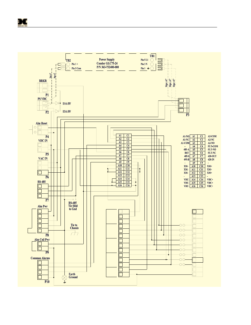
Model 610-N4X-SA
terminations should be completed prior to application of power. Shut-in controls may be omitted until
system test is complete.
14
13
12
11
10
9
8
7
6
5
4
3
2
1
14
13
12
11
10
9
8
7
6
5
4
3
2
1
CH1
P12-P16
CH1
4-20mA
FAULT
VDC-
Alarm 2
Alarm 1
Fault
Ou
t
+
-
COM
NC
ALM1
ALM2
GND
Shld
B(-)
A(+)
VD
C
VA
C
GND
VD
C
-
N
L1
-
+
+
RED +
BLK -
-
+
N
L1
Sen
sor
NO
COM
NO
NC
COM
NO
NC
mA
-
Typ. x 6
+
P11
Jumpers
Typical
CH2-CH6
GND-GRN
N-WHT
L1-BLK
PS VAC
Figure 2 Motherboard Schematic Wiring Diagram
610-N4X-SA Instruction Manual
Rev. 0.1
Page 4 of 8
See also other documents in the category Detcon Equipment:
- 12B (16 pages)
- FL-10 (7 pages)
- 10C Facilities (18 pages)
- 10C (29 pages)
- 10B (10 pages)
- 1212-N4X (9 pages)
- 812-N4X (9 pages)
- 1212B (5 pages)
- 612B (5 pages)
- 1610-N4X (28 pages)
- 1010-N4X (14 pages)
- 610-N4X (12 pages)
- 1610-N1 (4 pages)
- 810-N1-24VDC (10 pages)
- 410-N1-24VDC (4 pages)
- MCX-32-N1P (55 pages)
- RD-64X-N4X (41 pages)
- 880RA-N4X (36 pages)
- 880RA-N4X (23 pages)
- 880A-N1R (45 pages)
- 880A-N4X (50 pages)
- 880A-N4X (43 pages)
- X40-08-N4X (70 pages)
- 240 (33 pages)
- SW-AV1-N4 (12 pages)
- SW-AV2-DV1 (12 pages)
- A1V1 (9 pages)
- RXT-300 (47 pages)
- RXT-320 (31 pages)
- CXT-N4X (28 pages)
- SW-HMI-32-N4X (24 pages)
- SW-V1-DV2 (11 pages)
- SW-AV1-DV1 (14 pages)
- SW-AV2-DV2 (12 pages)
- SW-AV1-DV2 (12 pages)
- SmartWireless CX (33 pages)
- SmartWireless CXT (49 pages)
- CX-IR (38 pages)
- CX-DM (44 pages)
- CXT-IR (48 pages)
- CXT-DM (56 pages)
- P-1000 (28 pages)
- 1000 (32 pages)
- 1000_CO2 (32 pages)
- 1000_H2S (34 pages)