Detcon 610-N4X-SA User Manual
Page 11
Model 610-N4X-SA
Adding/Removing Control Modules
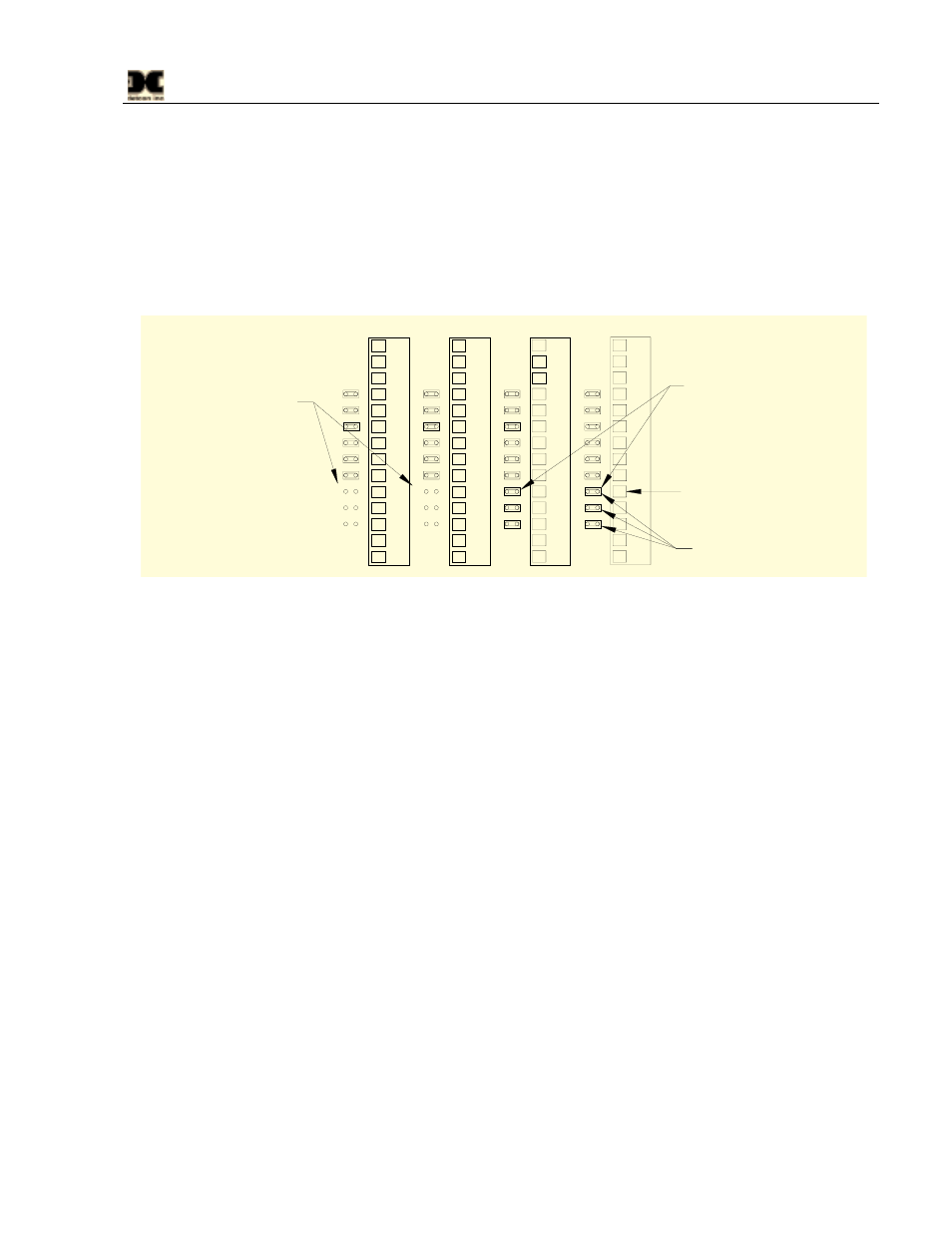
When adding or removing Control Modules it is imperative that the backplane jumpers are correctly removed
or added to insure proper operation of the fault alarm circuitry (see Figure 7). When removing a Control
Module, the jumpers for Fault (JPx-G, H, and I) directly to the left of the module being removed, must be
installed to allow proper signal flow and fault operation. When a Control Module is being added to the
configuration, the jumpers (JPx-G, H, and I) directly to the left of the module being installed, must be removed
to insure that the signal does not bypass the new module. Incorrect placement of jumpers will cause the fault
alarm circuit to operate incorrectly.
CH4
CH3
CH5
CH6
Jumpers installed for Control
Modules not installed in unit.
JP9
A
B
C
D
E
F
G
H
I
JP8
A
B
C
D
E
F
G
H
I
JP7
A
B
C
D
E
F
G
H
I
JP6
A
B
C
D
E
F
G
H
I
Jumpers removed for
Control Modules 7 and 8.
Fault Jumper positions
G, H, and I.
1
2
3
4
5
6
7
9
9
10
11
12
13
14
1
2
3
4
5
6
7
9
9
10
11
12
13
14
1
2
3
4
5
6
7
9
9
10
11
12
13
14
1
2
3
4
5
6
7
9
9
10
11
12
13
14
FAULT Output to Fault Relay
Figure 7 Backplane Configuration Jumpers
Model 10 Control Modules
A Model 10 control module may be changed by simply loosening its mounting screw and sliding the module
out of its card cage. See the Model 10 Instruction Manual for more information on the Model 10 controller.
Circuit Breaker/Power Switch
If the circuit breaker should trip due to a high current or over voltage, the circuit breaker can be reset by
cycling the breaker ‘OFF’ and back ‘ON’. If the breaker trips again, a problem has occurred that will need to
be alleviated before power can be restored.
Replacement of the circuit breaker is accomplished by disconnecting power from the unit, disconnecting the
wires going to the breaker, and removing the breaker from the Din-Rail. Replace the breaker and reconnect
the wires to the new breaker.
Power Supply
Replacement of the power supply is accomplished by, removing the 10 screws that secure the 610-N4X-SA
face plate, disconnect the two power supply plugs from their respective headers, remove the three screws
holding the power supply bracket to the Motherboard. Remove the four screws that hold the power supply
bracket to the power supply; disconnect the wires from the power supply and reassembly with the new power
supply. Reference Figure 6 for wiring details.
610-N4X-SA Instruction Manual
Rev. 0.1
Page 7 of 8