Detcon 1010SS-N4X User Manual
Page 7
1.6 S
TART
U
P
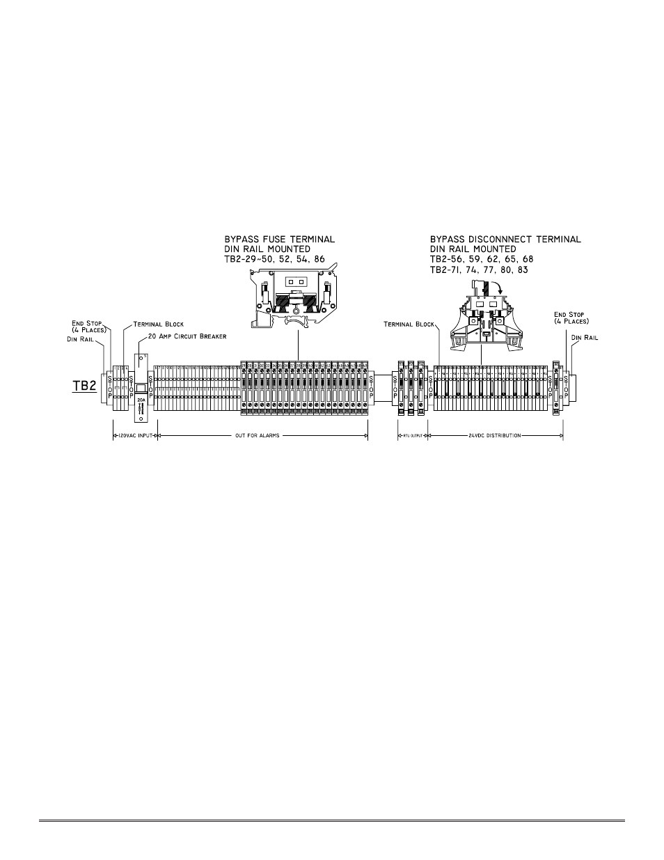
Upon completion of all field wiring per Figure 3 below, depress the top of the circuit breaker switch located on the
front panel. Be sure to push the switch portion of the breaker in all the way. It will make a slight snapping sound
to indicated it is properly engaged. Note that each Model 10 controller digital display illuminates. Varying readings
may occur during sensor warm-up. A 10 second alarm delay will occur on power up. Refer to Section 3.0 for addi-
tional sensor start-up detail.
1.7 M
AINTENANCE
& R
EPAIR
The Detcon Model 1010SS-N4X’s modular design allows for minimum down time during maintenance and/or
repair.
M
Mo
od
deell 1
10
0 C
Co
on
nttrro
oll M
Mo
od
du
ulleess
A Model 10 control module may be changed by simply loosening its mounting screw and sliding the module out
of its card cage. See Section 2.0 of the Detcon Model 10 “Single Channel Digital Control Module” manual for
more information on the 10 control module.
C
Ciirrccu
uiitt B
Brreeaak
keerr//P
Po
ow
weerr S
Sw
wiittcch
h
The 3 amp panel mount circuit breaker acts as both a resetable fuse device and a power switch. Push the top of the
breaker button in completely until you hear it snap in place to power up the 1010SS-N4X. Push the bottom of the
breaker button to turn power off. If the circuit breaker should trip due to a high current or overvoltage, the switch
will trip into a centered position. Push the top of the button back in securely to reset.
Replacement of the circuit breaker is accomplished by: removing the 10 screws that secure the 1010SS-N4X face
plate; disconnect the plug from its PCB mounted header; remove the wires from the plug; remove the locking wash-
er; push the circuit breaker out of the 1010SS-N4X face plate and then reassembly with the new component.
P
Po
ow
weerr S
Su
up
pp
pllyy
Replacement of the power supply is accomplished by: removing the 10 screws that secure the 1010SS-N4X face
plate; disconnecting the breaker plug from its header; disconnecting the two power supply plugs from their respec-
tive headers; removing the three screws that hold the power supply bracket the PCB motherboard; removing the
four screws that hold the power supply bracket to the power supply; disconnecting the wires from the power supply
and then reassembling with the new power supply.
Model 1010SS-N4X NEMA 4X Control Enclosure PG.7
Figure 3