Detcon 1010SS-N4X User Manual
Page 6
1.5 I
NSTALLATION
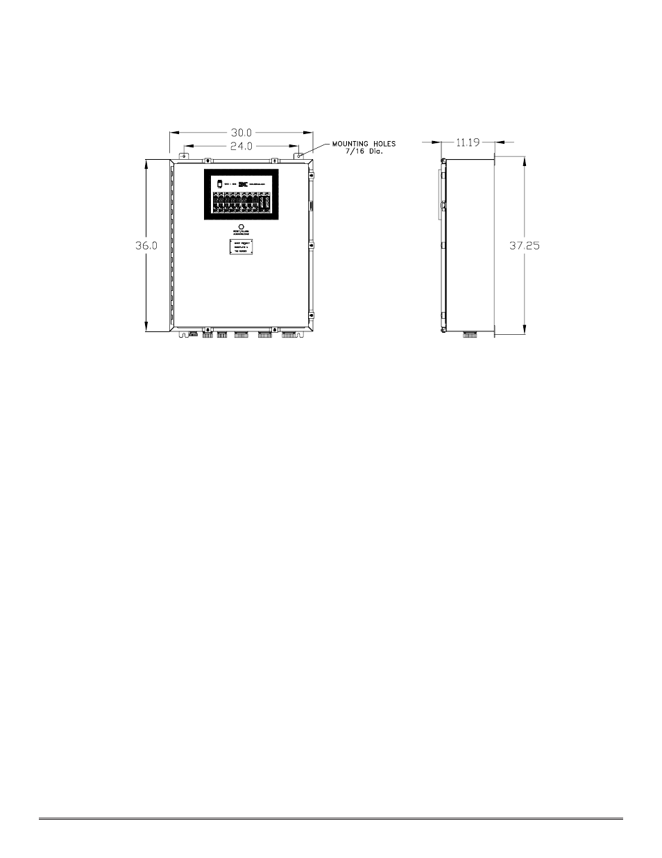
1. Securely mount the 1010SS-N4X enclosure in accordance with the drawing in Figure 2.
N
Noottee:: Reference Drawing #4120 for wiring terminations.
C
Caauuttiioonn:: Observe correct polarity when terminating all input/output field wiring. Failure to do so may result in
circuit damage on power up.
2. Connect 117VAC input to the terminal strip labeled “VAC IN” (L1, N, EARTH). If applicable, connect
220VAC. The power supply will accept both voltages.
3. If applicable, terminate earth ground to the earth ground lug located on the lower left of the panel.
4. Refer to installation and wiring detail of remote mount sensor assembly in Section 3.0. Terminate field wiring
from sensors to the 1010SS-N4X terminals per Drawing #4120. Sensor terminals are labeled (+, -, mA).
5. Install audible/visual alarm devices per wiring Drawing #4120.
6. If applicable, terminate the discrete 4-20 mA outputs to external device(s). Terminals are labeled “4-20 Out” (+
and –).
7. If applicable, terminate the RS-485 serial output to external device(s). Terminals are labeled “RS-485” (A+, B–,
and Shield). If applicable, terminate RS-485 Shield to Earth Ground via the jumper tab located to the left of
the RS-485 terminals. Place the jumper on the bottom 2 contacts to tie RS-485 shield to Earth Ground or
place the jumper tab on the top two terminals for storage.
Model 1010SS-N4X NEMA 4X Control Enclosure PG.6
Figure 2