Installation, Figure 1 alarm station dimensions, Figure 2 wiring diagram – Detcon AV1-N4X User Manual
Page 6: 0 installation, 12 or 24 vdc wiring
Model AV1-N4X
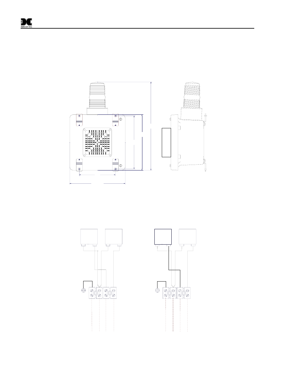
2.0 Installation
Securely mount the alarm station enclosure in accordance with the drawing in figure #1.
Connect wiring in accordance with the drawing in figure #2. To determine the proper voltage of the strobe and
siren, refer to the specifications label inside the enclosure
7.75"
7.75"
5"
7.375"
12.25"
Figure 1 Alarm Station Dimensions
STROBE
HORN
N
L1
N
L1
V
DC-
E
ar
th Gr
ound
Swi
tc
hed
VDC+ to Hor
n
S
w
itche
d V
DC+ to Strobe
120 OR 240
VAC WIRING
STROBE
HORN
N
L1
N
L1
L2
Neutr
al
E
ar
th G
ro
und
S
w
itc
hed
L1 to
Horn
S
w
itc
hed
L1
to Str
obe
12 OR 24
VDC WIRING
Figure 2 Wiring Diagram
AV1-N4X Instruction Manual
Rev. 1.1
Page 2 of 6
See also other documents in the category Detcon Equipment:
- 12B (16 pages)
- FL-10 (7 pages)
- 10C Facilities (18 pages)
- 10C (29 pages)
- 10B (10 pages)
- 1212-N4X (9 pages)
- 812-N4X (9 pages)
- 1212B (5 pages)
- 612B (5 pages)
- 1610-N4X (28 pages)
- 1010-N4X (14 pages)
- 610-N4X (12 pages)
- 1610-N1 (4 pages)
- 810-N1-24VDC (10 pages)
- 410-N1-24VDC (4 pages)
- MCX-32-N1P (55 pages)
- RD-64X-N4X (41 pages)
- 880RA-N4X (36 pages)
- 880RA-N4X (23 pages)
- 880A-N1R (45 pages)
- 880A-N4X (50 pages)
- 880A-N4X (43 pages)
- X40-08-N4X (70 pages)
- 240 (33 pages)
- SW-AV1-N4 (12 pages)
- SW-AV2-DV1 (12 pages)
- A1V1 (9 pages)
- RXT-300 (47 pages)
- RXT-320 (31 pages)
- CXT-N4X (28 pages)
- SW-HMI-32-N4X (24 pages)
- SW-V1-DV2 (11 pages)
- SW-AV1-DV1 (14 pages)
- SW-AV2-DV2 (12 pages)
- SW-AV1-DV2 (12 pages)
- SmartWireless CX (33 pages)
- SmartWireless CXT (49 pages)
- CX-IR (38 pages)
- CX-DM (44 pages)
- CXT-IR (48 pages)
- CXT-DM (56 pages)
- P-1000 (28 pages)
- 1000 (32 pages)
- 1000_CO2 (32 pages)
- 1000_H2S (34 pages)