Figure 6 120/240vac wiring diagram, Figure 7 24 vdc wiring, Wiring diagram (figure 6 or figure 7) – Detcon AV2-C1D2M User Manual
Page 10
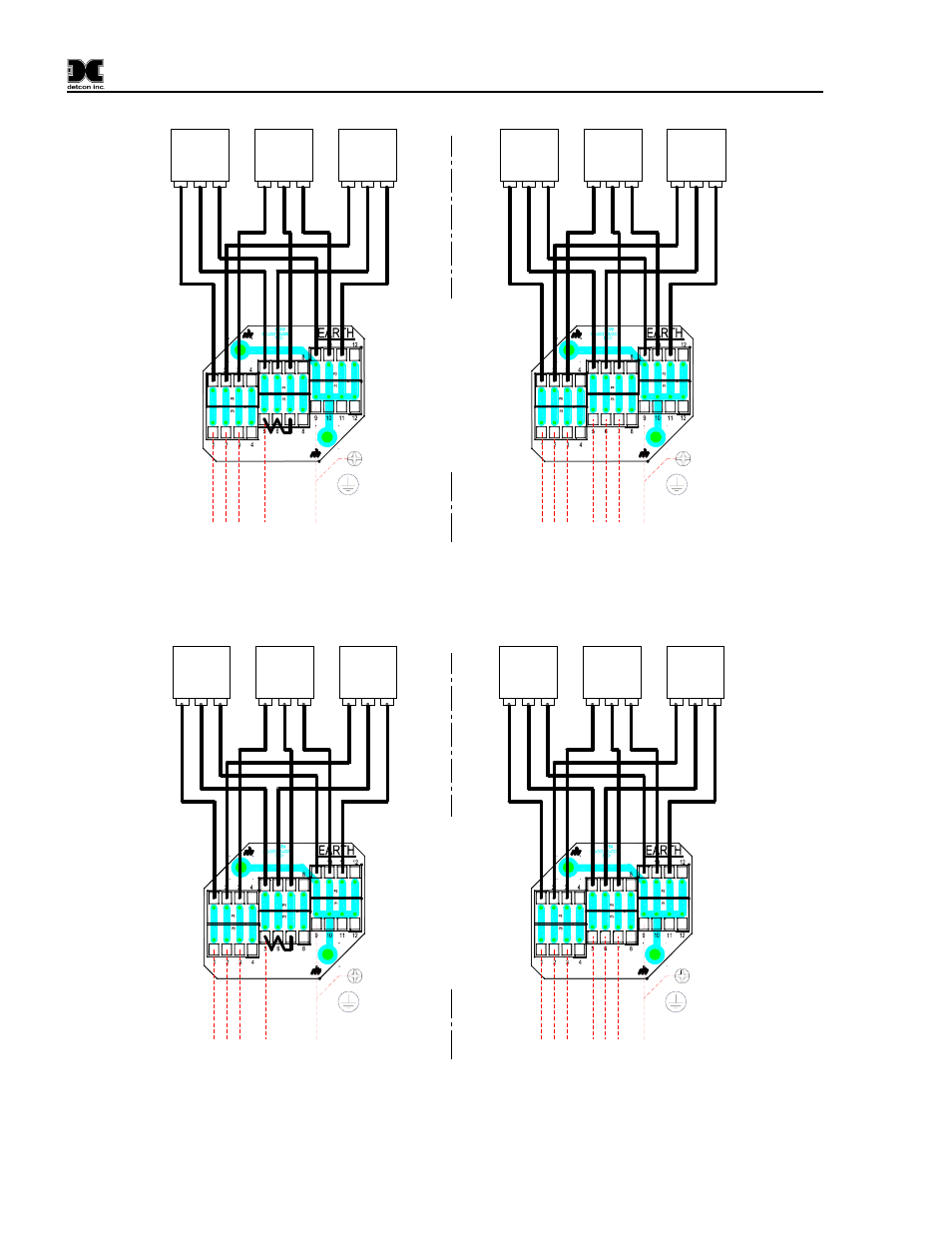
AV1/AV2-C1D2M
Customer Input Wiring
L1 S
iren
L1 S
trobe
1
L2 (N
eu)
GN
D
L1 S
trobe
2
Customer Input Wiring
L1 S
iren
L1 S
trobe
1
L2 S
trobe
1
GN
D
L1 S
trobe
2
L2 S
iren
L2 S
trobe
2
Optional
Standard wiring shown on
left.
Optional: Removal of jumper
between 5,6, and 7 for
discrete annunciator wiring
shown on right.
Ground can be connected to
the Ground Screw or the
connector.
Note: Strobe 2 not present
on AV!-C1D2C assembly
Bl
k
Bl
k
Bl
k
Wht
Wht
Wht
Grn/
Y
lw
Bl
k
Bl
k
Bl
k
Wht
Wht
Wht
Grn/
Y
lw
Wht
STROBE 1
STROBE 2
SIREN
L1 L2
G
L1
L1
L2
L2
G
G
STROBE 1
STROBE 2
SIREN
L1 L2
G
L1
L1
L2
L2
G
G
Grn/
Y
lw
Grn/
Y
lw
Grn/
Y
lw
Grn/
Y
lw
Figure 6 120/240VAC wiring diagram
Customer Input Wiring
L1 Si
re
n
L1 Strobe
1
L2 (Neu)
GN
D
L1 Strobe
2
Customer Input Wiring
L1 Si
re
n
L1 Strobe
1
L2 Strobe
1
GN
D
L1 Strobe
2
L2 Si
re
n
L2 Strobe
2
Optional
Standard wiring shown on
left.
Optional: Removal of jumper
between 5,6, and 7 for
discrete annunciator wiring
shown on right.
Ground can be connected to
the Ground Screw or the
connector.
Note: Strobe 2 not present
on AV!-C1D2C assembly
Bl
k
Bl
k
Bl
k
Wht
Wht
Wht
Gr
n/
Yl
w
Bl
k
Bl
k
Bl
k
Wht
Wht
Wht
Gr
n/
Yl
w
Wht
STROBE 1
STROBE 2
SIREN
L1 L2
G
L1
L1
L2
L2
G
G
STROBE 1
STROBE 2
SIREN
L1 L2
G
L1
L1
L2
L2
G
G
Gr
n/
Yl
w
Gr
n/
Yl
w
Gr
n/
Yl
w
Gr
n/
Yl
w
Figure 7 24 VDC Wiring
AV1/AV2-C1D2M Instruction Manual
Rev. 2.1
Page 6 of 8