Calibration port, 4 calibration – Detcon 971-071170-00L User Manual
Page 5
fault circuit board (this will allow for flow fault programming at the remote recording device or computer.
Because the pressure inside the sample and vent flow tubing differs according to the tubing length , the
flow fault circuit will require calibration after installation.
To calibrate the flow fault circuit, first determine at what point it is desired that the flow fault circuit is
activated. Typically, air flow should range between 500 and 1000 ml/min. (milliliters per minute) as seen
on the flow meter located on the left of the enclosure. It is recommended that the flow fault circuit be set to
activate at a flow of approximately 300 ml/m.
To adjust the flow fault first set the air flow at the point where you want the fault condition to activate.
Next turn the flow fault adjust potentiometer (PT1 as seen in the illustration on the previous page) clock-
wise until the flow fault LED illuminates and its relays fire. Make adjustments as necessary by increasing
and decreasing airflow until the flow fault function occurs at the desired set point. Once the flow fault cir-
cuit has been set, return the air flow to between 500 and 1000 ml/m.
NOTE: Because sample and vent tubing can become congested over a period of time, the flow fault func-
tion should be checked periodically and adjusted if necessary.
1.4 CALIBRATION
Model 971-071170-00L sensor assembly is calibrated prior to shipment and should therefore require mini-
mal adjustment at time of commissioning. However, it is recommended that a complete calibration be per-
formed on a periodic basis to assure optimum system performance. Refer to the sensor instruction manual
for gas type, range and sensor specific calibration instructions.
Note that the sensor instruction manual requires the removal of rain/splash guards for the application
of gas. This requirement will be superceded by the instructions below. The calibration adapter attached to
the sensor head should not be removed during calibration.
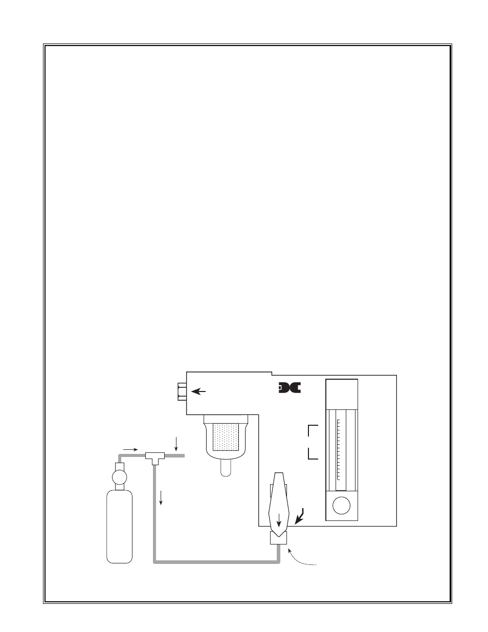
Required material:
1. Span gas cylinder containing gas as per instructions in the sensor instruction manual.
2. 1/4" Tee tubing fitting as shown in the illustratin below.
Detcon Model 971-071170-00L Gas Detection System PG.5
6" of
vent
tube
0
100
200
300
400
500
CAL PORT
SET
FLOW
SAMPLE
PORT
detcon inc.
HOUSTON, TEXAS
SAMPLE DRAW
GAS DETECTION SYSTEM
Calibration
Port
Fixed flow
regulator
Span gas
cylinder
Teflon
tubing
1/4"
Tee
500 ml/m
1000
ml/m