Flow fault circuit, Flow fault contacts, 2 start up – Detcon 971-071170-00L User Manual
Page 4: 3 flow fault detection
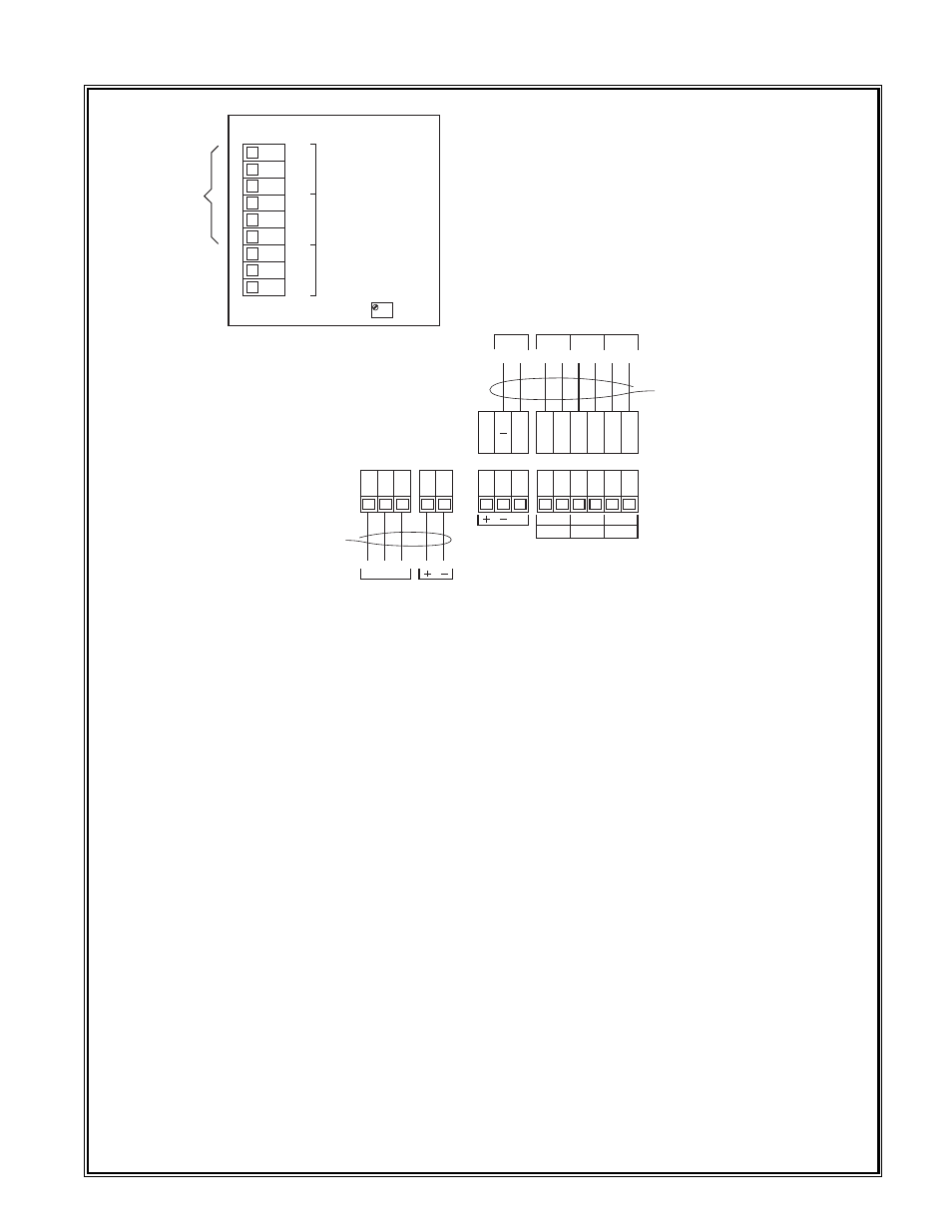
7. If applicable, connect alarm devices. Discreet alarm relay contacts are provided for three alarms: Fault,
Low and High. The contacts consist of common and choice of normally open or normally closed. Contact
output selections are jumper programmable on the sensor connector board. See the sensor manual for con-
tact ratings and other information.
8. If applicable, connect flow fault alarm wiring. Two sets of form C contacts (common, normally open and
normally closed) are provided. Relay contacts are rated 1 amp at 30VDC/.24 amp at 125VDC.
9. If applicable, connect RS-485 wiring.
The RS-485 requires 24 gauge, two conductor, shielded, twisted pair
cable between sensor and host PC. Use Belden part number 9841. Two sets of terminals are located on the
connector board to facilitate serial loop wiring from sensor to sensor. Wiring designators are +, –, and shield.
1.2 START UP
Upon completion of all tubing connections and field wiring turn on the power switch located on the enclo-
sure door. Note that the power lamp illuminates. If applicable, note that the sensor LCD indicator activates.
Varying readings may occur during sensor warm-up. Allow approximately 1 hour to stabilize (24 hours is best).
Also note air flow through the flow meter. Adjust the flow meter as necessary so that it falls between 500
and 1000 ml/m (milli liters per minute).
Assure that all field tubing connections are secure by obstructing the end of the sample line and observ-
ing that the flow meter decreases to “0” flow.
1.3 FLOW FAULT DETECTION
Flow fault detection consists of a flow fault circuit assembly located inside the enclosure and a door mount-
ed fault indicator lamp. If the air flow falls below a predetermined set point the following will occur: the
flow fault alarm relays will energize; an LED indicator mounted on the flow fault PCB will illuminate; the
door mounted flow fault lamp will illuminate; the 4-20mA signal will be opened via relay #1 on the flow
Detcon Model 971-071170-00L Gas Detection System PG.4
P7
P8
P6
P5
L1 L2 GND
mA
C NO/NC C NO/NC C NO/NC
117 VAC
IN
24 VDC
IN
Battery
Backup
SENSOR #1
FAULT
ALARM CONTACTS #1
ALARM 1 ALARM 2
ALARM DRY
CONTACTS
COM
NO/NC
COM
COM
NO/NC
NO/NC
FLT ALM 1 ALM 2
Flow
Fault
Circuit
COM
NO
NC
1
COM
NO
NC
2
COM
NO
NC
3
PT1
mA
4-20mA
Wire alarms and the 4-20mA output
signal to the plug-type connectors.
Wire 117 VAC & optional 24 VDC
backup to the lugless connectors.
Two discreet form C dry contacts
are provided (2 & 3) by the flow
fault circuit for alarm devices. The
first set of contacts (1) are
prewired to interrupt the 4-20mA
signal output in the event of a
flow fault. This will allow for flow
fault monitoring at any
controller/computer that the signal
is wired in to.
FLOW
FAULT
CONTACTS