Rl4 relay module, Figure 4 rxt transceiver figure 5 rl4 module, 5 rl4 relay module – Detcon SW-AV1-N4 User Manual
Page 7
SW-AV1-N4
SW-AV1-N4 I.M.
Rev. 0.0
Page 3 of 8
RF Channel
Selector Switch
MSD
LSD
Modbus
Address
Switches
RF Connector
Figure 4 RXT Transceiver
The radio module is housed in a black ABS box mounted inside the alarm station enclosure. The package
includes two PCAs mounted inside the black ABS box (radio PCA and Smart battery charging PCA). The
battery PCA includes circuitry to safely recharge the battery from a 24VDC input and a fuel gauge circuit to
monitor the charge remaining in the battery.
The radio PCA includes a 2.4Ghz radio and a rotary switch for setting the RF channel of the system (Figure 4).
Use a small screwdriver to rotate the switch until the arrow points to the desired RF channel number (16
channels available, 0h-Fh).
NOTE
All devices within the network must be on the same RF channel to operate correctly.
Each radio module is required to have a unique Modbus™ address. These addresses typically start at 01h and
continue sequentially for each Alarm Station in the gas detection system. The radio PCA includes a pair of
rotary switches to set this address (Figure 4). Refer to the Controller Manual for more information.
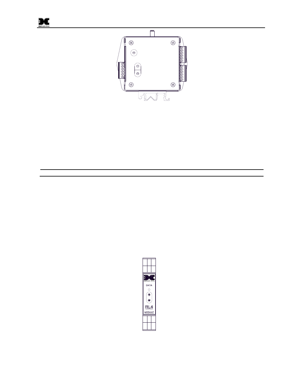
1.5 RL4 Relay Module
The alarm station utilizes the Detcon RL4 I/O Module to control the alarms (Figure 5). The RL4 is required to
have a unique Modbus™ address. These addresses typically start at 80h and continue sequentially for each
Alarm Station in the gas detection system. Refer to the Controller Manual for more information. The alarm
station is wired for proper operation of Alarm 1 and Alarm 2, with Alarm 1 wired to the Strobe, and Alarm 2
wired to the Horn.
RELAY
COMM
M
S
D
L
S
D
Alarm 1
Alarm 2
Alarm 3
Fault
Relay 4
Relay 3
Relay 1
Relay 2
Modbus
Address
Switches
NC
C
NO
NC
C
NO
C
NC
NO
C
NC
NO
MSD
LSD
Figure 5 RL4 Module